
Service manual


COMBAT
®
UH UNIT HEATER INSTALLATION OPERATION AND SERVICE MANUAL
36
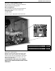
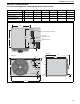
14.2 Burner Compartment
14.2.1 Burner Injectors
Remove flexible
air duct from spigot.
Viewing Port
Flame Probe
Burner
Compartment
Cover
Ignition Electrode
Remove screws and
pull off burner cover.
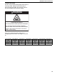
The burner compartment is a sealed
compartment. Following any work,
re-seal the compartment with the gas
pipe rubber seal fully in place and all
screws fitted and tight.
MODEL UH [A] [AS] 30 UH [A] [AS] 45 UH [A] [AS] 60 UH [A] [AS] 75 UH [A] [AS] 100 UH [A] [AS] 125
Orifice Quantity 2 3 4 5 6 7
Natural Gas (G20)
Orifice Marking4949494946 46
RG P/N 91930049 91930049 91930049 91930049 91930046 91930046
Propane (G31)
Orifice Marking 56 56 56 1.15 mm 1.25 mm 1.25 mm
RG P/N 91930056 91930056 91930056 91930115 91930125 91930125
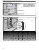
Remove manifold
screws and pull
out manifold.
Manifold
Burners
Orifices
Manifold
Mounting
Bracket
Gromet
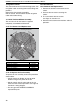
Unscrew
Orifices
Manifold
Marking
Ensure gas tight fitting of injectors.
Ensure correct alignment with burners.
Ensure all pipe joints are gas tight.