
Service manual


SECTION 10: OPERATION AND MAINTENENCE
23
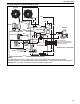
Figure 12: Automatic Burner Control Sequence
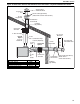
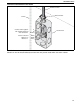
Figure 13: Gas Valve for Models UH (A) (AS) 30 - 45
Burner sequence for Ignition Control
Flame Signal
Start Gas Valve
Ignition Spark
Thermostat 24 V
SHUT DOWN
RUN
START
ts = 10 seconds
Signals Output By Control
Required Incoming Signals
Flue Fan
Pressure
Switch
P
C
NO
NC
30 Sec. Purge*
*Purge time begins at pressure switch change over.
Axial Fan
30 Sec. Delay 90 Sec. Delay
30 Sec. Post Purge
If at any stage the flame fails, the control will retry
for ignition. The control has four trials for ignition
before a one hour lockout.
Gas
Outlet
Outlet
Pressure
Pressure
Regulator