
Service manual
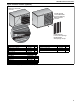


COMBAT
®
UH UNIT HEATER INSTALLATION OPERATION AND SERVICE MANUAL
10
SECTION 6: VENTING
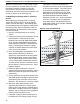
6.1 Changing Vent and Air Intake Orientation
The heater is sold with rear horizontal vent and air
intake connections as standard (only separated
combustion models have air intake connection). If
vertical vent and air intake connections are required,
follow the instructions on Page 38, Section 14.4.
6.2 Venting
This heater must be vented in accordance with the
rules contained in this manual and with the following
national codes and any state, provincial or local
codes which may apply: United States: Refer to
ANSI Z223.1 (NFPA 54) - latest revision; Canada:
Refer to CAN/CGA-B149.1 and B149.2 - latest
revision.
Any portion of vent pipe passing through a
combustible wall must have an listed thimble to
conform with the above codes.
The heater may be installed unvented in
certain circumstances according to building
ventilation codes. Refer to the above codes and
Page 11, Section 6.4 for further information.
Unvented operation also requires compliance with
the clearances to combustibles given on Page 4,
Figure 1.
The bottom of the vent or air intake terminal shall not
be located less than 1' (.3 m) above grade level.
The vent shall not terminate less than 7' (2.1 m)
above grade where located adjacent to public
walkways.
Vent terminal must be installed at a height sufficient
to prevent blockage by snow and building materials
protected from degradation by flue gasses.
Vent terminal must be beyond any combustible
overhang.
Secure all joints with corrosion resistant #8 x 3/8"
sheet metal screws.
For single wall venting, pressure sensitive aluminum
tape or silicone sealant must be used to seal all
joints.
Aluminum tape shall have a minimum temperature
rating of 400° F (204° C) and meet SMACNA AFTS-
100-73 standards. High temperature silicone
sealant must have a minimum temperature rating of
48° F (250° C).
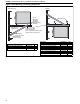
6.2.1 United States Requirements
Vent must terminate at least 3' (.9 m) above any
forced air inlet located within 10' (3.1 m).
Vent must terminate at least 4' (1.2 m) below,
4' (1.2 m) horizontally from, or 1' (.3 m) above any
door, operable window, or gravity air inlet into any
building.
The National Fuel Gas Code ANSI 223.1/NFPA 54
specifies a 4' (1.2 m) horizontal vent terminal
clearance from gas and electric meters, regulators
and relief equipment.
6.2.2 Canadian Requirements
The vent shall not terminate within 6' (1.8 m) of a
mechanical air supply inlet to any building.
The vent shall not terminate within 3' (.9 m) of a
window or door that can be opened in any building,
any non-mechanical air supply inlet to any building,
or of the combustion air inlet of any other appliance.
6.3 Vent Installation
For vented units, the vent must terminate outside of
the building.
Vents must be fully sealed and correctly sized for
the model. If the vent passes through a wall or
ceiling of combustible material, it must be enclosed
by a listed thimble and be separated from the
thimble by at least a 2" (5 cm) air gap.
For separated combustion models, vents and air
intakes must be a fully sealed system and correctly
sized for the model. Vent should be assembled as
detailed on Page 12, Figure 5 through Page 15,
Figure 10. The joints between the vent terminal and
the roof or wall must be properly sealed. If the vent
passes through a wall or ceiling of combustible
material, it must be enclosed by a listed thimble and
be separated from the thimble by at least a 2" (5
cm)air gap.
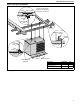
Vents and air intakes must be adequately
supported so that the heater does not bear the
weight of the pipes.
For vent termination See Page 12, Figure 5 through
Page 15, Figure 10.
WARNING
Fire Hazard
Some objects will catch fire or explode when placed
close to heater.
Keep all flammable objects, liquids and vapors the
required clearances to combustibles away from heater.
Failure to follow these instructions can result in death,
injury or property damage.