FOR YOUR SAFETY If you smell gas: 1. Open windows. 2. DO NOT try to light any appliance. 3. DO NOT use electrical switches. 4. DO NOT use any telephone in your building. 5. Leave the building. 6. Immediately call your local gas supplier after leaving the building. Follow the gas suppliers instructions. 7. If you cannot reach your gas supplier, call the Fire Department.
TABLE OF CONTENTS SECTION 1: Heater Safety...................................................... 2 SECTION 2: Installer Responsibility ..................................... 2 2.1 Clearances to Combustibles ........................................ 2 2.2 Corrosive Chemicals.................................................... 2 2.3 National Standards and Applicable Codes .................. 2 SECTION 3: Critical Considerations ..................................... 3 3.1 Basic Information .......................
TABLE OF FIGURES Figure 1: Installation Clearances and Clearances to Combustibles ............................................................. 4 Figure 2: Typical Installation of a Gas Fired Cabinet Heater ... 11 Figure 3: Typical Installation of a Oil-Fired Cabinet Heater ..... 12 Figure 4: Flue Termination ...................................................... 13 Figure 5: Offset Flues with 135° bends ................................... 13 Figure 6: Guy Wire ..............................................
Product Approval ROBERTS GORDON ® appliances have been tested and CE certified as complying with the essential requirements of the Gas Appliance Directive, the Low Voltage Directive, the Electromagnetic Compatibility Directive and the Machinery Directive for use with natural gas and LPG when installed, commissioned and maintained in accordance with these instructions. These instructions refer to gas appliances designed to operate in the European Union.
COMBAT® CABINET HEATERS INSTALLATION, COMMISSIONING, OPERATION AND SERVICE MANUAL SECTION 1: HEATER SAFETY clearances to combustibles. Affix the tag on a wall Your Safety Is Important to Us! near the heater. This symbol is used throughout the manual to notify you of possible fire, electrical or burn hazards. Please pay 2.2 Corrosive Chemicals special attention when reading and following the warnings in these sections.
SECTION 3: CRITICAL CONSIDERATIONS SECTION 3: CRITICAL CONSIDERATIONS 3.1 Basic Information Cabinet heaters are supplied with burners suitable for on/off operation as standard. As an option, oilfired burners are available with two-stage operation and gas-fired burners are available with full modulation. 3.2 Location and Suspension All models: • Are designed to be installed indoors within the heated space. Special versions are available for installation outdoors.
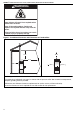
COMBAT® CABINET HEATERS INSTALLATION, COMMISSIONING, OPERATION AND SERVICE MANUAL WARNING Fire Hazard Some objects will catch fire or explode when placed close to heater. Keep all flammable objects, liquids and vapours the required distance away from the heater. Failure to follow these instructions can result in death, injury or property damage. Figure 1: Installation Clearances and Clearances to Combustibles .6 m .6 m 4m .6 m *.6 m *.6 m The flue pipe must have clearance from combustibles by 5 cm.
SECTION 4: SPECIFICATIONS SECTION 4: SPECIFICATIONS 4.
COMBAT® CABINET HEATERS INSTALLATION, COMMISSIONING, OPERATION AND SERVICE MANUAL 4.
SECTION 4: SPECIFICATIONS 4.3 Air Outlet and Flue Arrangements 4.3.1 Vertical and Horizontal Heaters - Free Blowing (top view) 040 030 015/020 165 165 0100 060/070/080 050 229 203 184 284 NOTE: Models 015-020 are fitted with 229 mm (9") diameter discharge heads as standard. Models 030-0100 are fitted with 356 mm (14") diameter discharge heads as standard. 4.3.
COMBAT® CABINET HEATERS INSTALLATION, COMMISSIONING, OPERATION AND SERVICE MANUAL 4.4 General Technical Data Table (all models) Appliance Category II 2H/L 3B/P Model 015 020 030 Electrical Supply* Main Fan Motor Type Motor Size (kW) Motor Pulley (PCD) NA Fan Pulley (PCD) NA 040 050 060 230 V / 50 Hz / 1 Ø Direct Drive Start Current Run Current Airflow Free Blowing 0.75 (Amps) (Amps) (m3/h) (ft3/min) 24 5.3 3398 2000 2.2 24 5.3 3398 2000 28 6.3 5097 3000 21 6.2 6796 4000 21 6.
SECTION 4: SPECIFICATIONS 4.
COMBAT® CABINET HEATERS INSTALLATION, COMMISSIONING, OPERATION AND SERVICE MANUAL 4.7 Technical Data - Ecoflam Oil-Fired Burners (burner reference "G") Model Gross Heat Input Heat Output 015 (kW) (Btu/h) x (1000) (kW) (Btu/h) x (1000) Burner Type Oil Pump Connections 020 55.5 73.3 189.4 250.1 47.4 61.2 161.8 208.9 Minor 8 030 93.2 318.0 78.4 267.4 Minor 12 (in) 040 050 060 070 080 0100 129.9 162.0 443.2 552.7 110.2 134.5 375.9 458.8 Minor 20 3/8 208.0 709.7 177.7 606.5 242.0 825.7 205.3 700.
SECTION 5: HEATER INSTALLATION SECTION 5: HEATER INSTALLATION 5.1 General Heaters are designed for floor standing vertical installation. Special versions supplied with steel channels to support the heater are available and may be mounted horizontally. When installed horizontally, the heater will normally lie on its left side when viewed from the burner. The heater should be placed on a firm, level, non-combustible surface that can support its weight. See Page 5, Section 4.1 for weight details. 5.
COMBAT® CABINET HEATERS INSTALLATION, COMMISSIONING, OPERATION AND SERVICE MANUAL Figure 3: Typical Installation of a Oil-Fired Cabinet Heater 1m Minimum Flues up to 200 mm dia. are fitted with Bird Screens, over 200 mm with a Rain Cap.
SECTION 6: FLUE INSTALLATION SECTION 6: FLUE INSTALLATION 6.1 Flue Installation WARNING Fire Hazard Some objects will catch fire or explode when placed close to heater. Keep all flammable objects, liquids and vapours the required distance away from the heater. Figure 6 through Page 14, Figure 9. The joints between the flue and the roof or wall must be properly sealed.
COMBAT® CABINET HEATERS INSTALLATION, COMMISSIONING, OPERATION AND SERVICE MANUAL Figure 6: Guy Wire Figure 8: Flue and Roof Detail Screws, four typical. Over 2 m use Guy Wires Roof Clamp ring Roof Rain Collar Seal Rain Collar joint with high temperature silicon sealer Heat Sealed Flash Band Wall Use adequate support to prevent heater from carrying the weight of the flue.
SECTION 7: AIR SUPPLY SECTION 7: AIR SUPPLY 7.1 Air Supply It is important to ensure adequate air supply at all times for both combustion and heating requirements in accordance with BS 6230 for UK installations and the latest revisions of applicable standards and local and national codes. 7.2 Isolated Equipment Rooms Ventilation must prevent the temperature of isolated equipment room from exceeding 32°C as well as prevent any negative air pressure within the room.
COMBAT® CABINET HEATERS INSTALLATION, COMMISSIONING, OPERATION AND SERVICE MANUAL SECTION 8: FUEL PIPING 8.1 Connections Connect the heater to the gas supply, ensuring that the final connections are as follows: • Gas supply pipe is run in medium or heavy gauge tubing in compliance with local and national codes. • The gas supply pipe is adequately sized to carry the total volume of gas for the complete installation.
SECTION 8: FUEL PIPING 8.2 Fuel Oil Supply 8.2.1 Fuel Storage Tank The fuel storage tank should be located outside the building as close as possible to the heater. The tank must be installed per local and national codes. 8.2.4 B. M. Oil Lifter Where a gravity feed system cannot be used, a B. M. oil lifter may be used for small installations up to the equivalent of a single model 050 on minimum lift or a single model 020 on maximum lift. The fuel output from the oil lifter is gravity fed. The B. M.
COMBAT® CABINET HEATERS INSTALLATION, COMMISSIONING, OPERATION AND SERVICE MANUAL Figure 12: Pressurised System Installation - Duplex System Pressure Gauge Relief Valve Check Valve Check Valve Stop Valve Stop Valve For Fuel Tanks above Pump Set No. 1 Pump Stop Valve Pressure Reducing Valve No. 2 Pump Stop Valve Burner Duplex Pump Set Check Valve Storage Tank Below Ground (The system shown has one pump for run and the other for standby.
SECTION 9: WIRING AND ELECTRICAL INFORMATION SECTION 9: WIRING AND ELECTRICAL INFORMATION 9.1 Electrical Supply 9.2.2 Positioning Room Thermostats or Roberts-Gordon Control A 230 V 50 Hz 1 Ø supply is required for all heater Models 015 to 030 connected to the heater terminals A room thermostat or Roberts-Gordon control L1, N and Earth. should be mounted on a wall or column at a height of approximately 1.5-1.
COMBAT® CABINET HEATERS INSTALLATION, COMMISSIONING, OPERATION AND SERVICE MANUAL 2. The control will then adjust the burner input continuously to attempt to maintain the temperature set on the control. 3. If the temperature continues to rise with the burner operating at minimum fire, the control will turn off the burner until the temperature falls again, and the burner will restart.
SECTION 9: WIRING AND ELECTRICAL INFORMATION 9.
COMBAT® CABINET HEATERS INSTALLATION, COMMISSIONING, OPERATION AND SERVICE MANUAL 9.
SECTION 9: WIRING AND ELECTRICAL INFORMATION 9.
COMBAT® CABINET HEATERS INSTALLATION, COMMISSIONING, OPERATION AND SERVICE MANUAL 9.
SECTION 9: WIRING AND ELECTRICAL INFORMATION 9.
COMBAT® CABINET HEATERS INSTALLATION, COMMISSIONING, OPERATION AND SERVICE MANUAL 9.
SECTION 9: WIRING AND ELECTRICAL INFORMATION 9.
COMBAT® CABINET HEATERS INSTALLATION, COMMISSIONING, OPERATION AND SERVICE MANUAL 9.
SECTION 9: WIRING AND ELECTRICAL INFORMATION 9.
COMBAT® CABINET HEATERS INSTALLATION, COMMISSIONING, OPERATION AND SERVICE MANUAL 9.
SECTION 9: WIRING AND ELECTRICAL INFORMATION 9.
COMBAT® CABINET HEATERS INSTALLATION, COMMISSIONING, OPERATION AND SERVICE MANUAL 9.
SECTION 10: COMMISSIONING SECTION 10: COMMISSIONING Installation, service, commissioning and annual inspection of the heater must be done by a contractor qualified in the installation and service of gas or oil-fired heating equipment. Read this manual carefully before installation, commissioning, operation or service of this equipment. WARNING 2. Check the correct fuse size is fitted in the local supply isolator. See Page 8, Section 4.4. 10.1.
COMBAT® CABINET HEATERS INSTALLATION, COMMISSIONING, OPERATION AND SERVICE MANUAL Figure 13: Combination Thermostat (all models) 100 0 12 60 80 Set Point 3 Limit Set to 110°C Set Point 1 Fan Off Set to 38°C C° 20 40 Set Point 2 Fan On Set to 60-65°C See Page 34, Section 10.2.5 and repeat until the burner fires. 10.2.4 Initial Setting NOTE: Skip this step for models 015 to 030.
SECTION 10: COMMISSIONING 3. Check gas flow rate at gas meter. 10.3 Control - Gas-Fired Heaters For High/Low and modulating burners, follow the general sequence as described below and also have extra functional stages related to air damper positions. Refer to the burner manufacturers instructions for further detail. Gas burners have only one pressure switch, which is configured to cover combustion air and reaction to increases in combustion chamber pressure.
COMBAT® CABINET HEATERS INSTALLATION, COMMISSIONING, OPERATION AND SERVICE MANUAL Figure 15: Motor Starter (models 040 -100 and Thermal Overload (models 060 - 100) Wire Connecting Overload Switch to Coil Line Connections Contactor Load Connections Thermal Overload Overload Reset Button Overload Connection Overload Scale (motor current amps) Overload Adjusting Level Figure 16: Gas Train Circuit for Dungs Gas Valves (all models) Models 15 to 30 - All types of valve Models 40 to 100 - All types of v
SECTION 10: COMMISSIONING Figure 17: Dungs Gas Valve 10.4 Gas Valves Dungs Combination Gas Valve All model 015 - 030 gas-fired burners operate as direct main flame ignition and have no separate start gas train. All other models operate with a first stage start gas flame supplied from a start gas train containing a start gas pressure regulator and two safety shut-off valves, for all gas types.
COMBAT® CABINET HEATERS INSTALLATION, COMMISSIONING, OPERATION AND SERVICE MANUAL 10.5.1 Pressure Switch WARNING Electrical Shock Hazard Use extreme caution while commissioning. Failure to follow these instructions can result in death or electrical shock. Setting of the pressure switch must only be carried out as part of a complete commission which includes combustion testing. Remove the cover of the pressure switch.
SECTION 10: COMMISSIONING 10.7.2 Sequence of Operation The operating sequence is as follows: With the external controls on and calling for heat, the burner fan and electric ignition will switch on. After a combustion air purge of approximately twelve seconds, the oil solenoid valve will open and the burner will fire. After another five seconds, the electric ignition is turned off and the burner will go into its normal run position. The photo cell continuously monitors the safe presence of the flame.
COMBAT® CABINET HEATERS INSTALLATION, COMMISSIONING, OPERATION AND SERVICE MANUAL SECTION 11: USER INSTRUCTIONS 11.1 User Instructions The COMBAT® Cabinet heaters are fully automatic and operate from the external controls fitted on site. The only user controls at the heater are the: Fan Run Button - See Page 40, Figure 20. Burner lockout reset button - See Page 41, Section 11.2.2. Limit thermostat reset button - See Page 40, Figure 20.
SECTION 11: USER INSTRUCTIONS Explosion Hazard If control locks out, do not make more than 3 attempts to restart the heater. Dangerous fuel mixtures can build up. The fault must be traced and repaired by a registered installer or service engineer. Failure to follow these instructions can result in death, injury or property damage. 11.2.2 Burner Lockout Reset Button The red warning light built into the burner control box will illuminate when the control has gone to lockout.
COMBAT® CABINET HEATERS INSTALLATION, COMMISSIONING, OPERATION AND SERVICE MANUAL FOR YOUR SAFETY If you smell gas: 1. Open windows. 2. DO NOT try to light any appliance. 3. DO NOT use electrical switches. 4. DO NOT use any telephone in your building. 5. Leave the building. 6. Immediately call your local gas supplier after leaving the building. Follow the gas suppliers instructions. 7. If you cannot reach your gas supplier, call the Fire Department.
SECTION 12: SERVICING SECTION 12: SERVICING 12.1 Servicing Instructions After commissioning, the heater will require maintenance to be carried out annually. If the heater is used in a dirty or dusty area, more frequent maintenance may be necessary. Installation, Service and Annual Inspection of the heater must be done by a contractor qualified in the installation and service of gas or oil-fired heating equipment. 12.
COMBAT® CABINET HEATERS INSTALLATION, COMMISSIONING, OPERATION AND SERVICE MANUAL SECTION 13: CONVERSION BETWEEN FUELS 13.1 General All COMBAT® Cabinet heaters may be operated on fuel oil, natural gas or propane gas, depending on which burner type has been fitted. Any conversion between fuels must be done by a contractor qualified in the installation and service of gas or oilfired heating equipment.
SECTION 14: TROUBLESHOOTING SECTION 14: TROUBLESHOOTING 14.1 General WARNING Explosion Hazard Installation must be done by a registered installer/ contractor qualified in the installation and service of gas-fired heating equipment or your gas supplier. Failure to follow these instructions can result in death, injury or property damage.
COMBAT® CABINET HEATERS INSTALLATION, COMMISSIONING, OPERATION AND SERVICE MANUAL 14.2 Troubleshooting for Oil Burners (see manufacture’s instructions) WARNING Electrical Shock Hazard Do not touch ignition components. Voltage from ignition components is high. Failure to follow these instructions can result in death or electrical shock. START Assuming fuel & electrical supplies are ON Does the burner fire? No Check if the control fuse in No the heater has blown. Yes Check supply to burner motor.
SECTION 14: TROUBLESHOOTING 14.3 Troubleshooting for Gas Burners (see manufacturer’s instructions) WARNING Electrical Shock Hazard Do not touch ignition components. Voltage from ignition components is high. Failure to follow these instructions can result in death or electrical shock. START Assuming fuel & electrical supplies are ON. Does the burner fan run? No Is the pressure switch at rest? (no contact open) No See Section 10.5.1 for setting. Yes Fault lies elsewhere.
COMBAT® CABINET HEATERS INSTALLATION, COMMISSIONING, OPERATION AND SERVICE MANUAL 14.4 Troubleshooting for Flame Supervision System The flame supervision system is different for gas-fired and oil-fired heaters but may be tested in a similar way. Gas-fired heaters use a rectification flame probe to monitor the flame. Oil-fired heaters use a photo sensitive cell to monitor the flame.
14.5 Troubleshooting for Solenoid Valves Circuit START Is there pressure on the outlet of the valve when the Yes valve should be closed? Is there an electrical supply Yes to the valve terminals? Fault lies elsewhere. Investigate and correct. No Valve faulty. Replace with correct type. No Does valve open at the correct time? No Is there an electrical supply Yes to the valve terminals? Fault lies elsewhere. Investigate and correct. No Valve faulty. Replace with correct type.
14.7 Troubleshooting for Main Fan (3 Ø) START Main fan will not operate following warm up period of heat exchanger. Check for 400 V three phase No supply at main terminals. Fault lies elsewhere. Yes Check for 230 V at terminals No 1 to N Press in white button of fan/limit thermostat and retest. No Fault lies elsewhere. Yes Check calibration of the fan thermostat. The dial should indicate the approximate temperature of the sampled air. Yes Check the setting of the fan thermostat as in Section 5.1.
SECTION 15: REMOVAL AND REPLACEMENT PARTS SECTION 15: REMOVAL AND REPLACEMENT PARTS See warnings and notes on Page 43, Section 12 before removing or replacing parts. a new fuse into the spring clips. To replace the holder, remove the fuse, pull off the two tag connectors from either end, and then unscrew the central screw. Reverse these instructions to refit. 15.1 Burner Components To remove the burner from the heater: 1. Unplug the burner electrical supply from the heater. 2.
COMBAT® CABINET HEATERS INSTALLATION, COMMISSIONING, OPERATION AND SERVICE MANUAL 5. Check the correct rotation of the fan as on Page 33, Section 10.1.5. NOTE: The direct drive fan unit motor can only be replaced as a complete fan/motor assembly. Figure 22: Combination Fan/Limit Thermostat WARNING Fire Hazard Break-off link must be removed from replacement thermostat. Heat exchanger damage may result. Failure to follow these instructions can result in death, injury, property damage or product damage.
SECTION 16: PARTS LIST SECTION 16: PARTS LIST The following items are recommended as spares which may be required during routine service and replacement of the air heater. There is also a list of parts in the burner manufacturer’s manual which relates to the parts required for the packaged burner fitted to the heater. 015 020 030 040 050 060 070 080 0100 16.
Attach this information to the wall near the ROBERTS GORDON® heater ® Read the Installation, Commissioning, Operation and Service Manual thoroughly before installation, operation or service. WARNING OPERATING INSTRUCTIONS 1. STOP! Read all safety instructions on this information sheet. 2. Open the manual fuel valve in the heater supply line. 3. Turn on electric power to the heater. 4. Set the thermostat to desired setting (above ambient temperature). The automatic starting sequence begins.