
Installation Guide

1518
CORD COVER ASSEMBLY INSTRUCTIONS:
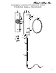
1. Remove mounting plate (A) from backplate (C) by removing screws (I). Set screws (I) aside.
2. Determine desired location for light xture on wall. Hold mounting plate (A) in a level position on desired wall location. Using a pencil, mark the location
of the holes (H) at the top and bottom of the mounting plate onto the wall.
3. Drill small holes at marked locations on the wall. Holes should be sized so wall anchors (O), provided, t snug inside the opening. Insert wall anchors into
drilled holes.
4. Thread mounting screws (N) through holes (H) in the mounting plate, and into wall anchors (O).
5. Slide backplate (C) over mounting plate (A). Thread screws (I) back into holes at the top and bottom of backplate (C) to secure xture to the mounting
surface.
7. Thread cord cover (K) into the bottom of backplate (C). Thread cord cover (L) onto cord cover (K).
8. Insert one 150 WATT MAX. Type A, Medium Base bulb into the socket (G).
9. Attach lens frame (F) to loop (D) by aligning holes in the top of lens frame (F) on either side of the hole in loop (D). Unscrew the cap from screw (E) and
insert through aligned holes in lens frame and loop. Replace cap onto screw (E) and turn until hand tight.
10. Insert three prong plug (M) into wall outlet.
11. Control power to the xture by using the switch on the cord.
IMPORTANT SAFETY INSTRUCTIONS:
* These instructions are provided for your safety. It’s important that all safety instructions are read before beginning installation of xture.
* We STRONGLY recommend installation by a licensed electrician.
* Turn off power at switch before replacing bulbs, making sure xture has had sufcient time to cool down.
* Do not connect the electricity until lamp is fully assembled.
* If any special control devices are used with this xture, follow the instructions carefully to assure full compliance with N.E.C. requirements. If there are any
questions, contact a qualied electrical contractor.
ASSEMBLY INSTRUCTIONS FOR YOUR
FINEAS WALL SCONCE
DIRECT WIRE ASSEMBLY INSTRUCTIONS:
1. SHUT OFF MAIN ELECTRICAL SUPPLY FROM THE MAIN FUSE BOX/ CIRCUIT BREAKER. IT IS RECOMMENDED THAT A LICENSED
ELECTRICIAN INSTALL THIS FIXTURE.
2. Remove mounting plate (A) from backplate (C) by removing screws (I). Set screws (I) aside.
3. Cut the switch and the three prong plug (M) from the end of the electrical cord.
4. Remove cord covers (K) and (L) from the electrical cord. From the back side of backplate (C), pull the electrical cord up through hole in the bottom of the
backplate.
5. Cut the cord to the desired length for making an electrical connection. At least six inches of wire will be needed to make proper electrical connection.
6. Thread plug (J) into the hole in the bottom of backplate (C).
7. Lift mounting plate (A) to the wall outlet box. Once mounting plate is properly aligned and level, use a pencil to mark the locations of holes (H) at the top
and bottom of the mounting plate on the wall.
8. Drill small holes at marked locations on the wall. Holes should be sized so wall anchors (O), provided, t snug inside the opening. Insert wall anchors into
drilled holes.
9. Carefully pull the wiring from wall outlet box. Thread the wires through the center hole in mounting plate (A).
10. Afx mounting plate (A) to wall outlet box with mounting screws (B) provided.
11. For additional support thread mounting screws (N) through holes (H) and into wall anchors (O).
12. Lift xture to mounting plate and make proper electrical connections described in steps 13-15 A LICENSED ELECTRICIAN IS RECOMMENDED.
13. Connect ground (green or silver in color) wire from xture to ground wire in the outlet box. Fasten wires together with wire nut (P) and tightly wrap the
connection with electrical tape.
14. Attach hot wire from xture (black in color or smooth side of wire) to hot wire from outlet box. Fasten wires together with wire nut (P) and tightly wrap
connection with electrical tape.
15. Attach neutral wire from xture (white in color or ribbed side of wire) to neutral wire from outlet box. Fasten wires together with wire nut (P) and tightly
wrap connection with electrical tape.
16. Carefully push wire connections back into wall outlet box.
17. Slide backplate (C) over mounting plate (A). Thread screws (I) back into holes at the top and bottom of backplate (C) to secure xture to the mounting
surface.
18. Insert one 150 WATT MAX. Type A, Medium Base bulb into the socket (G).
19. Attach lens frame (F) to loop (D) by aligning holes in the top of lens frame (F) on either side of the hole in loop (D). Unscrew the cap from screw (E) and
insert through aligned holes in lens frame and loop. Replace cap onto screw (E) and turn until hand tight. loop. Replace cap onto screw (E) and turn until
hand tight.
19. Reconnect main electrical supply from the fuse box/ circuit breaker and test the xture.
* To clean, use a soft dry cloth. Do not use any chemical or abrasive cleaners. *