
Datasheet


Aluminum Electrolytic Capacitors
NO. ITEM SPECIFICATION
2. 6
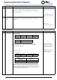
Surge test
Rated surge voltage shall be applied (swich on) for 30 ± 5 seconds and
then shall be applied (swich off) with discharge for 5 ± 0.5 min at room
temperature . This cycle shall be repeated for 1000 cycles. Duration of one
cycle is 6 ± 0.5 minutes .
2. 7
Capacitance change : within
± 20% of the initial specified
value.
Dissipation factor : lessthan
200% of the initial specified
value.
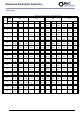
The maximum A.C.current having frequency of 100K Hz which can be applied to
the capacitor at 105±2℃ continuously.Peak voltage not to exceed rated
D.C.voltage.
Leakage current :
within initial specified value.
3. Mechanical characteristics
NO. ITEM
SPECIFICATION
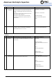
3. 1
Lead strength
(A) Tensile strength:
wire lead terminal:
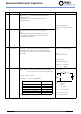
d (mm)
≦0.45
0.5 ~ 0.8
0.8<d≦1.25
load (Kg)
0. 51
1.0 2.0
snap-in terminal:
d (mm)
load (Kg)
The capacitor shall withstand the constant tensile force specified
between the body and each lead for 10 seconds without damage
either mechani
cal or electrical.
(B) Bending strength:
wire lead terminal:
d (mm)
≦0.45
0.5 ~ 0.8 0.8<d≦1.25
load (Kg)
0. 25
0.51 1.0
snap-in terminal:
When the capacitance is
measured, there shall be
no intermittent contacts,
or open- or short- circui-
ting.
There shall be no such
mechanical damage
as
terminal damage etc.
With the capacitor in a vertical position apply the load specified axially to
each lead . The capacitor shall be rotated slowly from the vertical to the
horizontal position, back to the vertical position. The 90° in the opposite
direction and back the original position . Performance of capacitor shall not
have changed and leads shall be undaged .
Applicable
ripple
current
S>1
1.0
2. 5
0.5<S≦1
TEST METHOD
cross section area of
terminal (m㎡)
force
(Kg)
TEST METHOD
snap-in terminal
2.0
Distrelec Schweiz AG, Grabenstrasse 6, 8606 Nänikon, Switzerland, T +41 44 944 99 11, info@distrelec.com, distrelec.com