
User's Manual

REV. 1.10/2002
RMT LtdRMT Ltd
RMT LtdRMT Ltd
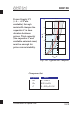
DX6106
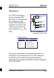
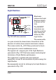
Light Emitters
Electronic
scheme for Light
Emitters driving
is shown in Fig.
3.26.
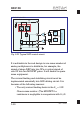
The MOSFET
transistors are
used as a switch
keys which are
driven by TTL
logic levels.
The resistors
in a gate circuits fix closed state of transistors at the
absence of activity from external electronic scheme.
The sense resistor (0.22 Ohm) produces the feed-
back signal for current stabilization circuit.
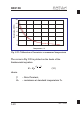
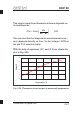
The typical volt-ampere plot of the Light Emitter is
presented in Fig. 3.27. Dark area means technological
deviations of Light Emitter performance.
The capacitor together with other external
capacitors, serves for accumulation of pulse energy for
Light Emitter.
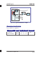
Recommended circuit for driving by the Light Emitter is
presented in Fig. 3.28.
R
C
G
S
R
Fig 3.26. LED drive switches
+
X2
6
X2
4
X2
5
X2
3
X2
1
R
E
C
R
S
R
G
R
G
GATEM
GATER
SOURCE
GND
+ELED
3-24