
User's Manual

REV. 1.10/2002
RMT LtdRMT Ltd
RMT LtdRMT Ltd
DX6106
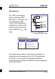
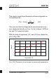
It is obvious that the scheme responds to temperature
in a nonlinear manner. At over a limited
temperature range the
scheme response as linear.
It is also obvious that the solution of this problem
should be based on the usage of a microcontroller. A
look-up table for temperature measurements
l
The table may be located in the Optical Unit’s EEPROM
or in another memory chip. The base points of this
table must correspond to the set of operating
temperatures of the Optical Unit (See Chapter
“Calibration”).
the same time
it is possible to consider
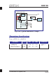
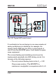
inearization must be formed in the external memory.
The recommended external circuit schematic is
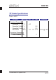
presented in Fig. 3.25. Not worse than 12-bit resolution
A/D converters (ADCs) are recommended.
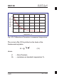
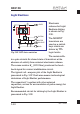
In a vicinity of each point the response of the scheme
should be linearized. The total number of points must
be equal to the number of calibration tables (the
number of operating temperatures ranges).
3-22