
User's Manual
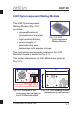

Construction of Optical Unit
RMT LtdRMT Ltd
RMT LtdRMT Ltd
DX6106
Thermoelectric Cooler
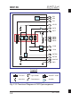
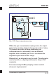
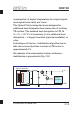
The TEC circuit diagram is
presented in Fig. 3.17.
Driving by TE cooler requires
particular attention.
First of all, the operation of TE
cooler directly affects
performance parameters of
Optical Unit and gas sensor
based on it.
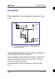
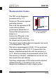
Second, the TE cooler is the
component which consume
the largest part of power (Fig. 3.18).
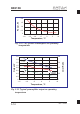
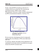
The output signal of Photodetector depends very much
on its temperature (Fig. 3.19).
This ratio is approximately 100%/20 °C. It is equivalent
to the temperature drift 1%/0.2 °C. It means that if the
thermo-stabilization should be with the accuracy of
0.1°C, then the accuracy of measurements will be 0.5%.
The accuracy of thermo-stabilization must be not less
than required for gas sensing.
Operating temperature of TE cooler must be selected
optimal (from Fig. 3.18 and Fig. 3.19): too low
temperature stabilization leads to higher power
Fig. 3.17. Schematics
of TE cooler in
X2
2
TEC
X2
1
GND
3-13