
User's Manual
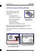
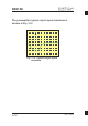
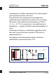

Construction of Optical Unit
RMT LtdRMT Ltd
RMT LtdRMT Ltd
DX6106
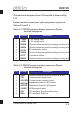
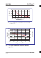
Table 3.2. DX6106 s pins
function description
ystem interface connector X1
Pin Mnemonic Description
1
2
3
4
5
6
7
8
–5VIN
+5VIN
GNDA
GNDA
OUTS
GNDA
OUTT
GNDA
– 5V supply input
+ 5V supply input
Ground reference point for analog circuitry and
Ground reference point for analog circuitry and
Ground reference point for analog circuitry and
Photodetector output
Thermistor output
Ground reference point for analog circuitry and
Table 3.3. DX6106 s pins
function description
ystem interface connector X2
1
2
3
4
5
6
7
8
GND
TEC
SOURCE
GATEM
GATER
+ELED
SCL
SDA
Ground reference point for power circuitry
Cooler power supply input
Current sense resistor output
Measuring channel LED enable
Reference channel LED enable
LEDs power supply
I C interface. Synchronization line
2
I C interface. Data line
2
Pin DescriptionMnemonic
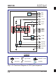
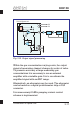
The functional diagram of the 6102 module is drawn in Fig.
3.13.
System interface connectors’ pins assignment is given in
Tables 3.2 and 3.3.
3-9