R325PE Single Axis Driver with Indexer and Encoder Reader User Manual And Commands Guide Version 1.01 RMS Technologies 2533 N. Carson St. #4698, Carson City, NV 89706-0147 RMS Technologies R325P Single Axis Driver Manual Page 1 Version 1.
Thank you for purchasing the R325PE Single-Axis Driver with Indexer. This product is warranted to be free of manufacturing defects for one (1) year from the date of purchase. PLEASE READ BEFORE USING Before you start, you must have a suitable step motor, a DC power supply suitable for the motor and a current resistor. The power supply voltage must be between 4 times and 20 times the motor's rated voltage. DISCLAIMER The information provided in this document is believed to be reliable.
R325PE User Manual Product: Version: Date: R325PE 1.01 5/29/2013 Version History Version Date Description of Changes 1.00 01/31/2013 New User Manual 1.01 05/29/2013 Updated enable/disable pin description on page 8. RMS Technologies R325P Single Axis Driver Manual Page 3 Version 1.
Table of Contents 1. FEATURES........................................................................................... 5 2. ELECTRICAL SPECIFICATIONS...................................................................... 5 3. OPERATING SPECIFICATIONS ..................................................................... 6 4. MECHANICAL SPECIFICATIONS ................................................................... 6 6. CONNECTION SPECIFICATIONS ...........................................................
1. FEATURES • • • Single Axis Driver with indexer for Bipolar step motors Encoder readout function available Operates from +12 to 48 VDC • Phase currents from 0.3 to 3.0 Amp Peak NOTE: Phase current of 2.7 Amp and above REQUIRES an additional heatsink, make sure the temperature of the bracket does not exceed 45° C.
3. OPERATING SPECIFICATIONS Maximum Step Frequency: Operating Temperature: 2.5 MHz Low end – 0° C High end – Dependent on case temperature, bracket temperature must not exceed 45° C Automatic Motor Holding Current reduction available from 0.3 to 2.5 Amps Logic Timing Minimum Step Pulse Width 200 nanoseconds Minimum Step Low Time 200 nanoseconds Maximum Power-Down Recovery Time 20 milliseconds 4. MECHANICAL SPECIFICATIONS Size: 3.00” x 2.75” x 1.42” Weight: 3.2 oz Mounting: Four #6-32 screws, 2.42” x 2.
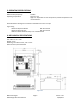
5. PIN ASSIGNMENTS Mating Connectors P1 P2 P3 AMP AMP Phoenix P1 – RS485 bus Interface 640441-3 640441-5 1803675 P1 Configuration Pin No Function 1 A Input (+ve) 2 Ground 3 B Input (-ve) Table 5.1 P2 – Encoder Interface Pin No 1 2 3 4 5 P2 Configuration Function Ground Index A +5VDC B Table 5.2 P1 & P2 Location of Pin 1 Inage 5.1 A motor with a single ended optical encoder must be used in order for the encoder feedback function to work.
CAUTION: Connecting Motor phases (A, A Bar, B, B Bar) to the incorrect location while the R325P is powered will cause the board to burn. Be sure to insert motor phases into Pins 6 through 9, in the order of A, A Bar, B, and B Bar. It is recommended that power is connected last, so that all connections can be checked before power up. 6. CONNECTION SPECIFICATIONS When using the Driver Only portion of the R325PE, use the dip switches for step resolution and current settings.
Pin 6: Phase A Motor Connection CAUTION: Connecting Motor phases (A, A Bar, B, B Bar) to the incorrect location while the R325P is powered will cause the board to burn. Be sure to insert motor phases into Pins 6 through 9, in the order of A, A Bar, B, and B Bar. It is recommended that power is connected last, so that all connections can be checked before power up.
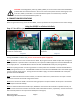
Figure 6.1 Using the R325P with more than 5V You can choose to supply the optos with the R325P’s internal 5V supply by jumping pins 1 to 4. But if you choose to use more than 5V, for example, a 24V supply and the step pulse train is also a 0 to 24V low-high signal, please use the following recommended resistor to limit the current to 10 mAmps. Note: no resistor will be needed on the actual opto supply line, pin 1.
Configure the R325P using the DIP Switch R325P DIP Switch Settings Run Current Function SW1 SW2 SW3 SW4 0.3A ON ON ON ON 0.4A OFF ON ON ON 0.5A ON OFF ON ON 0.6A OFF OFF ON ON 0.8A ON ON OFF ON 1.0A OFF ON OFF ON 1.2A ON OFF OFF ON 1.4A OFF OFF OFF ON 1.6A ON ON ON OFF 1.8A OFF ON ON OFF 2.0A ON OFF ON OFF 2.2A OFF OFF ON OFF 2.4A ON ON OFF OFF 2.6A OFF ON OFF OFF 2.8A ON OFF OFF OFF 3.0A OFF OFF OFF OFF Table 6.3 WARNING: Current of 2.
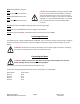
Communicating with the R325PE Step 1: Move all dipswitches to the OFF position. Place jumper on Pins 1 & 2. Jumper is placed closest to the LED. Move ALL dipswitches to the OFF Position Inage 6.3 1. Connect P1 to PC via RS485-232 Converter Card or USB485 Converter Card. 2. Set up HyperTerminal by selecting correct COM port 3. Settings for HyperTerminal is as follows: 57600, 8 bits, None, 1, None 4.
USB485 Converter Card Figure 6.3 7. COMMAND TABLES The R325PE can also be used as an indexer with closed loop controls. Basic controller commands can be used but users cannot store programs to the unit. This unit is commonly used with a user-created GUI or PLC’s that can communicate commands via ASCII and serial port.
General Operation Commands Function Absolute Position Current Position Current Velocity Direction Velocity* Firmware Revision Home Axis Move Status Position Move Step Back Step Forward Stop Motion Velocity Move * Query/Command C Q/C Q C Q C Q C C C C Q Code AP CP CV DV FR HA MS PM SB SF SM VM Value Numeric Numeric Numeric Numeric Numeric Numeric Numeric Numeric None None None Numeric Table 7.
8.
Table 8.1 – List of Commands Command Operand (Case Sensitive) HOMING & POSITIONING HA 0 = Forward 1 = Reverse CP +/– 2,147,483,646 ZP - VELOCITY & ACCELERATION AC 1 - 250 Example #AHA1 Motor turns in the reverse direction #ACP1000 Sets the current position to be 1000 #ACP Returns the current position of the motor #AZP Description Home Axis - Command Only - Causes the motor to move at the preset Start Velocity (SV) in the direction set by the command value.
Command Operand Example (Case Sensitive) VELOCITY & ACCELERATION (cont.) AP +/– #AAP1000 2,147,483,646 Moves to the 1000th position. CV +/- 50,000 #ACV DV +/- 50,000 #ADV1000 #ADV-1000 MS 0 -2 Rotates CW at 1000 pps then CCW at 1000 pps. Use this to rotate CW & CCW.
Command Operand Example (Case Sensitive) VELOCITY & ACCELERATION (cont.
Command Operand (Case Sensitive) SETTING CURRENT HI 0-3000 RI 300 - 3000 Example #AHI300 Sets the Hold Current to 300mA (0.3A) #ARI1000 Sets the run current to 1000 mA (1.0 Amp) HT 100 -5000 #AHT100 Sets the Hold Timeout to 100 mS STORAGE & RECALL LD - #ALD Loads all the default values Description Hold Current - Command or Query - 0 to 3000 Default = 300 - Reads or sets the motor Holding Current in 100 milliamps increments. The value does not round.
Command Operand (Case Sensitive) SD - Example #ASD Saves data MISC PF 0, 1, 2, 3 #ACD1 Sets Mixed Mode damping to 15% MICROSTEPPING SR 1, 2, 4, 8, 16, 32, 64, 128, 256 #ASR4 Sets the step resolution to 4x Description Save Data - Command Only - This command causes a set of parameter values to be written to non-volatile memory. On power up the last set of values written are set to be the parameter initial values.
Command Operand (Case Sensitive) QUERY COMMANDS FR - MA 65 - 90 Example #AFR #AMA88 Sets the unit address to 88 (‘X’) RS 0-1023 #ARS Reads the switch inputs TI - #ATI Reads the switch inputs BR 9600 – 57600 #ABR9600 Sets the Baud Rate to 9600 bps Description Firmware Revision - Query Only - Returns 3 digit part code followed by 3 digit firmware revision value. Reply *AFR325PEV100 //R325PE firmware revision 1.00 My Address - Command or Query Default = 65 - Reads or sets the unit address.
Command Operand Example (Case Sensitive) ENCODER VERSION COMMANDS EM 1, 2 #AEM2 Sets the Encoder Mode to 2 EI 0, 1 #AEI1 EL 0 - 16777215 Encoder Installed True #AEL400 Sets the encoder line count to 400 CE +/- 16777215 (Motor Position in Encoder counts) #ACE EA 1, 2 #AEA2 EP 0 – 16777215 Sets Error Action to Correct Mode #AEP10 *ACE12345 Description Encoder Mode – Command or Query, Default = 2 - Reads or sets the operating mode of the Encoder Interface IC.
ER 0 - 16777215 #AER Error Read – Query Only - Returns the current Encoder Error value. If the product of Encoder Lines and Encoder mode is larger than the product of Motor Steps and Step Resolution, then the error is in Encoder Counts. Otherwise it is in Steps. Motor Fullsteps (per revolution) – Command or Query Default = 200 Reads or sets the number of Fullsteps per motor revolution, i.e. A 1.8° motor will have a Fullstep count of 200.
9. Troubleshooting R325P is not functioning correctly Try putting the R325P into TEST mode by placing a jumper on Pins 3 & 4 of J1 as shown below. The motor should twitch back and forth slightly if the R325P is functioning properly. R325P not moving the motor (Step/Dip) Verify that the 5V is being supplied to Pin 1.
10. Appendix A: Recommended Cable Recommended Cable Configurations: DC Supply to Driver Cable length, wire gauge and power conditioning devices play a major role in the performance of your RMS Technologies Driver and Motor. NOTE: The length of the DC power supply cable to the Driver should not exceed 50 feet. Example A – Cabling Under 50 Feet, DC Power Example A demonstrates the recommended cable configuration for DC power supply cabling under 50 feet long.
NOTE: These recommendations will provide optimal protection against EMI and RFI. The actual cable type, wire gauge, shield type and filtering devices used are dependent on the customer’s application and system.
Recommended Cable Configurations: Driver to Motor Cable length, wire gauge and power conditioning devices play a major role in the performance of your Driver and Motor. NOTE: The length of the DC power supply cable between the Driver and the Motor should not exceed 50 feet. Example A demonstrates the recommended cable configuration for the Driver to Motor cabling under 50 Feet long. Correct AWG wire size is determined by the current requirement plus cable length.
* 0.5 MH is a typical starting point for the Common Mode Line Filters. By increasing or decreasing the value of L you can set the drain current to a minimum to meet your requirements.
11. Appendix B: PF Value For applications requiring ultimate smoothness of motion and extreme accuracy, the R325P driver can be programmed via RS485 to change the Percent Fast Decay rate, or, the PF value. The Percent Fast Decay default is 2, or a mixed mode of 48%. Mixed mode is a damping technique done to the driver IC.
• • • PF value 3 Slow speeds Bad waveform • • • PF value 1 Fast speeds Bad waveform RMS Technologies Page 30 R325PE Single Axis Closed loop Driver/Indexer Manual Version 1.