
Manual


RMS Technologies Page 9 Version 1.20
R325IE Single Axis Controller/Driver Manual 02/13/2006
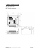
6. PIN ASSIGNMENTS
A 12-pin pluggable terminal strip connector P1 provides power and the step and
direction control functions for the module. All of these signals are optically isolated.
Open-collector drives are required to provide pulses for Step, levels for Direction,
and Disable. The common +ve supply can be +ve 5 to 30 VDC with respect to the
signal input; however if the supply is greater than 5 VDC then a resistor must be
inserted in series with each signal line to limit the current to 10 mA.
P1 Configuration
Pin No Function
1 Common +ve External
2 Step (in)
3 Direction (in)
4 +5 VDC Internal
5 Disable (in)
6 Motor A+ (out)
7 Motor A- (out)
8 Motor B+ (out)
9 Motor B- (out)
10 Fault (out)
11 Power Ground
12 Power Positive
P1 Connector – Pin 1 Location
CAUTION: Connecting Motor phases (A, A Bar, B, B Bar) to the incorrect location
while the R325 is powered will cause the board to burn. Be sure to insert motor
phases into Pins 6 through 9, in the order of A, A Bar, B, and B Bar. It is
recommended that power is connected last, so that all connections can be
checked before power up.
A separate three pin connector P3 is provided for the RS485 bus interface
P3 Configuration
Pin No Function
1 A Input (+ve)
2 Ground
3 B Input (-ve)
Mating Connectors
P1 Phoenix Contact 1803675
P2 Amp 640441-5
P3 Amp 640441-3
JP1 – Jumper on Pins 7 & 8 (Default)