
Manual


RMS Technologies Page 15 Version 1.20
R325IE Single Axis Controller/Driver Manual 02/13/2006
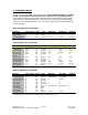
9. COMMAND TABLES
To begin using the R325IE in command mode, insure that the jumper is located
on Pin 7 & 8 of JP1 and that switches 8, 9, and 10 are in the OFF position,
setup must be made with an RS485 connection and communication can take place
using Windows HyperTerminal. When using the Driver Only portion of the R325IE,
first remove the jumper located on JP1, use the dip switches for step resolution and
current settings.
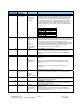
Basic Configuration Commands
Function Query/New Code Value Minimum Maximum Default
Load Defaults N LD None - - -
Save Data N SD None - - -
Module Address Q/N MA Numeric 65 (A) 90 (Z) 65 (A)
Axis Configuration Commands
Function Query/New Code Value Minimum Maximum Default
Acceleration Q/N AC Numeric 1 250 10
Hold Current Q/N HI Numeric 0 3000 300
Hold Timeout Q/N HT Numeric 100 5000 5000
Min. Velocity Q/N MV Numeric 256 15,000 256
Percent Fast
Decay
Q/N PF Numeric 0 3 2
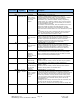
Run Current Q/N RI Binary 300 3000 1000
Read Switches Q RS Numeric 0 15 -
Step Resolution Q/N SR Numeric 1 256 16
Start Velocity Q/N SV Numeric 256 15,000 1,000
Velocity Limit Q/N VL Numeric 256 15,000 15,000
Zero Position N ZP None - - -
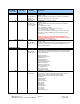
General Operation Commands
Function Query/New Code Value Minimum Maximum Default
Absolute Position N AP Numeric -2147483646 2147483647 -
Current Position Q/N CP Numeric -2147483646 2147483647 -
Current Velocity Q CV Numeric 0 50,000 -
Firmware Rev. Q FR Numeric - - -
Home Axis N HA Numeric 0 1 -
Move Status Q MS Numeric 0 2 -
Position Move N PM Numeric -2000000000 2000000000 -
Step Back N SB None - - -
Step Forward N SF None - - -
Stop Motion N SM None - - -
Velocity Move * Q VM Numeric -50,000 50,000 -
* Velocity Moves in the range –249 to 249 are not legal except zero