
Manual


RMS Technologies Page 13 Version 1.20
R325IE Single Axis Controller/Driver Manual 02/13/2006
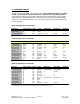
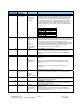
Configure the R325IE using the DIP Switch
R325IE DIP Switch Settings
In addition to the Jumper on Pin 7 & 8 on JP1, the Switches 8, 9, and 10 must be “OFF” in
control mode. If using Step & Direction mode remove the jumper.
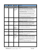
Run Current
Function SW1 SW2 SW3 SW4
0.3A ON ON ON ON
0.4A OFF ON ON ON
0.5A ON OFF ON ON
0.6A OFF OFF ON ON
0.8A ON ON OFF ON
1.0A OFF ON OFF ON
1.2A ON OFF OFF ON
1.4A OFF OFF OFF ON
1.6A ON ON ON OFF
1.8A OFF ON ON OFF
2.0A ON OFF ON OFF
2.2A OFF OFF ON OFF
2.4A ON ON OFF OFF
2.6A OFF ON OFF OFF
2.8A ON OFF OFF OFF
3.0A OFF OFF OFF OFF
WARNING: Current of 2.7 Amp and above REQUIRES an additional heatsink, make sure
the temperature of the bracket does not exceed 45° C
Hold Current (Percent of Run Current)
Function SW5 SW6
0% ON ON
33% OFF ON
66% ON OFF
100% OFF OFF
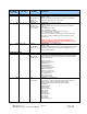
Step Resolution
Function SW7 SW8 SW9 SW10
Full Step* OFF OFF OFF OFF
2X ON OFF OFF OFF
4X ON ON OFF OFF
8X ON OFF ON OFF
16X ON ON ON OFF
32X ON OFF OFF ON
64X ON ON OFF ON
128X ON OFF ON ON
256X ON ON ON ON
*The power must be turned OFF when switching in and out of Full Step mode.
Notes:
1. Switches 8, 9 , and 10 must be set to ‘OFF’ to use the R325IE in control mode. This is
in addition to installing the jumper on JP1 Pins 7 and 8.
2. Installing a jumper on JP1 Pins 9 and 10 runs the factory test routine