
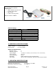
User Manual

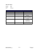
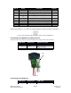

Pin # Color Function Input*
1 Red +V (Main Power In)
2 Black I/O 1
3 Brown RS485B (-)
4 Black/Whit
e
RS485A (+)
5 Orange Switch Closure to GND (IN) 4
6 Green GND (-V of main power in)
7 White Opto Sensor Phototransistor (IN) 3
8 Blue I/O 2
9 Yellow Opto Sensor LED (Power Out)
Table 2: Pin Assignments
*Inputs are labeled 1, 2, 3 and 4 for programming the ‘Halt’ and ‘Skip’ Commands.
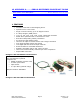
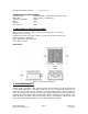
Figure 2: DB-9 Female Cable Connector (When viewing R256 DB-9)
Connecting to the RS232 card (RoHS version)
See Section 9 for connecting to old non-RoHS version, using a red 4-pin connector
R256 pin# R256 color *RS232 card pin#
4 Black/white 1 (RS485A)
6 Green
2 (GND connect to Power
Supply Ground)
3 Brown 3 (RS485B)
Table 3
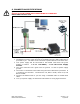
Figure 3
Connecting to the USB card
R256 pin# R256 color *USB pin#
4 Black/white 1 (RS485A)
RMS Technologies Page 8 Version 1.05
R256 Controller Manual 4/3/2009
Pin 1