
User Manual
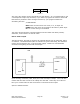
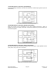
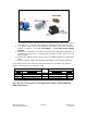

7. The RS232 converter card connects to the R256 using the DB-9 cable that is
provided to you. The red 4-Pin connector is placed onto the converter card.
8. Your power supply will be connected to the RS232 card where the green
header is located. + is for +12-40VDC, - is for the Power Supply
Ground.
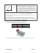
9. The motor is connected to the R256 using the other cable that is provided. It
is a white 4-pin connector. The Red wire is A, Blue is A Bar, Green is B, and
Black is B Bar.
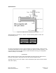
10. Connect the RS232 card to your PC using a standard female to female DB-9
cable.
11. Turn your power supply on and follow instructions for using HyperTerminal.
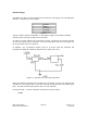
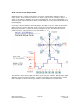
If you have the old 4-pin connector, below describes how to retrofit your cable in
order to work with the new converter card:
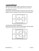
Old 4-Pin cable Connect
to
New 3-Pin cable
Pin # Color/function Color/function Pin #
Pin 1 Red (PWR)
No connection --
Pin 2 Green (GND)
Green (GND) Pin 2
Pin 3 Brown RS485 B (+)
Brown RS485 B (+) Pin 3
Pin 4 Black/white RS485 A (-)
Black/white RS485 A (-) Pin 1
Note: Be sure to send power to the R256 unit via Pins 1 and 6 (PWR and
GND, respectively)
RMS Technologies Page 27 Version 1.05
R256 Controller Manual 4/3/2009