
User Manual
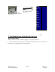
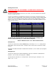

Changing the Address of the Controller
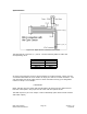
Use a screwdriver to turn the dial so the arrow points to the desired Address. Use
this number when programming commands. For example, /1P1000R
Figure 14: Address Dial
Note: New RoHS compliant boards have a Black dial instead of a Red one.
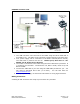
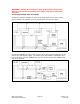
Connecting the Accessory Pieces
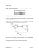
If you have purchased the Designer’s Kit, there is a Red Push Button and an Optical
Sensor included. Follow the schematics below in order to properly assemble
accessory pieces.
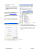
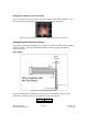
Push Button
Figure 15: Push Button Schematic
It is best to solder the Push Button to Pin 5 which corresponds to Input 4, then
solder Pin 6 (Power Ground) to the other side of the push button.
Input 1 Pin 2
Input 2 Pin 8
RMS Technologies Page 17 Version 1.05
R256 Controller Manual 4/3/2009