R208 Microstepping Driver User Manual Version 1.22 RMS Technologies 2533 N. Carson St.
Thank you for purchasing the R208 driver. This product is warranted to be free of manufacturing defects for one year from the date of purchase. Technical Support for Lin Enigneering, a distributor for RMS Technologies By Telephone: 408-919-0200 (Mon.-Fri., 8:00 a.m.-5:00 p.m.) On the Web: www.linengineering.com Our technical support group is glad to work with you in answering your questions.
R208 User Manual Product: Version: Date: R208 1.22 8/31/2007 Version History Version Date 1.16 02/02/2005 1.17 10/17/2005 1.18 11/09/2006 Updated equation for Voltage Reference. Typographical Errors 1.19 2/2/2007 Standardization of User Manuals 1.20 6/7/2007 1.21 8/24/2007 1.22 8/31/2007 Added min. order qty for R20805; updated description of opto supply.
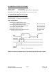
TABLE OF CONTENTS 1. FEATURES 5 Automatic Current Cutback Feature 5 2. ELECTRICAL SPECIFICATIONS 6 3. OPERATING SPECIFICATIONS 6 Operating Temperature Logic Input Timing 6 6 4. MECHANICAL SPECIFICATIONS 7 Dimensions 7 5. PIN ASSIGNMENTS 8 6. CONNECTION SPECIFICATIONS 8 List of Parts Mating Connectors 8 8 Adjusting the Output Current 9 How to Connect Alternative Step Resolution Connection 7.
1. FEATURES • • • • • • • • • • • • • • • • Bipolar Step Motor Driver Low Cost Small size 2.464” x 1.932” x .848” (62.59 x 49.07 x 21.
2. ELECTRICAL SPECIFICATIONS Supply Voltage: Peak Current: +12 to 24 VDC 0.35 to 2.0 Amps OR 0.25 to 1.4 Amps/Phase 100% duty cycle is OK as long as bottom of unit is 50°C or less 3.
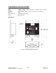
4. MECHANICAL SPECIFICATIONS Size: Weight: Mounting: Cover: Plate/Heatsink: Color: 2.464” x 1.932” x .848” (62.59 mm x 49.07 mm x 21.54 mm) 3.68 oz (104 g) Four screws, 1.622” x 2.003” (41.20 mm x 50.88 mm) Steel Aluminum, Anodized Black Exterior Dimensions Figure 2: R208 Dimensions Diagram RMS Technologies R208 Microstepping Driver Manual Page 7 Version 1.
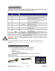
5. PIN ASSIGNMENTS A DB-9 female connector cable receives power and provides the control connections for the R208 Driver. Active signals are optically isolated. An open-collector drive is required to provide pulses for Step, levels for Direction and Disable/Enable. PIN # COLOR FUNCTION DESCRIPTION (#26 AWG Lead) 1 2 Red Black 3 Brown 4 Black/White 5 Orange 6 Green 7 White 8 Blue 9 Yellow +V SR1 Input Motor Supply Voltage. +12 to +24 VDC Step Resolution 1.
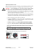
Adjusting the Output Current Before connecting a step motor to this driver, use the following procedure to check the output current of the R208 unit. The default output current is set at 1.0 Amp. WARNING! – To avoid damaging your step motor with the default setting, the output current should be adjusted before connecting the step motor. 1. Ensure that the step motor is not connected to the R208 unit. Do not supply pulse input to the R208 unit while adjusting the Output Current.
How to Connect To connect the R208 according to Figure 4, begin by connecting your step motor to the R208, for details on how to make that connection refer to Section 8 – Motor Connections. Next, connect the DB-9 mating connector to the R208. If using a function generator, take the positive end and connect it to Pin 9 (Step) and connect the negative end of the generator and connect it to the negative of the +5 VDC power supply.
Alternative Step Resolution Connection It is possible to change the microstepping resolution by using the signal from the controller. Figure 5: Alternative Step Resolution Connection By sending a high signal to Pin 2 and/or Pin 3, the connection between these pins will be effectively closed with Pin 7. This will change the microstepping resolution. Please refer to the Table 3 for Step Resolution Settings. NOTE: The microstepping resolution should not be changed on the fly, loss of step may occur.
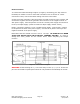
7. CONFIGURING AND CONTROLLING THE R208 Signal Control Specifications Default Settings Current 1.4 Amp Step Resolution 8x microstep Direction of rotation Counterclockwise Current Cutback Enabled Switch Read step pulse from Falling Edge (-) Step Resolution SR1 SR2 (Black) (Brown) Table 3: Default Settings The R208 is set to these default settings when Pins 2, 3, 4, and 5 are left open and untouched.
Internal Schematic The R208 has 3 optically isolated logic inputs. These inputs are isolated to minimize or eliminate electrical noise coupled onto the drive control signals. Each input is internally pulled-up to the level of the optocoupler supply and may be connected to sinking outputs on a controller or a PLC. These inputs are: Enable/Disable (Pin 4) Direction (Pin 5) Step Clock (Pin 9) Figure 6: Optically Isolated Inputs Within the Driver lies three 680 Ω Resistors and three Optocouplers.
8. MOTOR CONNECTIONS Step Motors have 4, 6, or 8 wires. To better understand how to connect your step motor with your R208 Driver, follow the Figures below for the corresponding motor. NOTE: The dots indicate the starting position of the wires when wound. 4 Lead Wire Motor Connection Connect one set of windings to the A terminals. Connect the other set of windings to the B terminals. If the set of windings is unclear, take a pair of wires; use an ohmmeter to check for continuity.
Figure 7.3: 6 Lead Wire Full Winding Connection 8 Lead Wire Motor Connection (Parallel Connection) Eight wire motors can be connected in two ways: Parallel and Series. When in parallel, the wires are simply connected such that the beginning of each winding are connected together. Figure 7.4: 8 Lead Wire Parallel Connection 8 Lead Wire Motor Connection (Series Connection) Be sure to set the drive current to exactly half of the motor’s rated parallel current rating when using the series connection.
9. TROUBLESHOOTING & FAQ When you first encounter a problem, the first step is to identify which component is the cause of the problem. You can do this by swapping out individual components and verifying if they work independently. Make sure that you have connected all the wiring correctly, this is a common cause of most problems Problems and Solutions • The Motor is in Holding Position, but does not rotate: This means that Power is being supplied to the driver and motor, so the power supply is OK.