R101 Single Axis Driver/Indexer User Manual And Commands Guide Version 1.31 RMS Technologies 2533 N. Carson St.
Thank you for purchasing the R101 Single-Axis Driver/Indexer. This product is warranted to be free of manufacturing defects for one (1) year from the date of purchase. Technical Support for RMS Technologies By Telephone: 877-301-3609 (Mon.-Fri., 8:00 a.m.-5:00 p.m.) On the Web: www.rmsmotion.com Via Email: support@rmsmotion.com PLEASE READ BEFORE USING Before you start, you must have a suitable step motor, a DC power supply suitable for the motor and a current resistor.
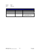
Product: Version: Date: R101 1.31 10/1/2007 Version History Version Date 1.20 05/07/2005 1.30 06/12/2007 Updated #AMV < #AVL 1.31 10/1/2007 Added info on internal resistors and recommended resistors for opto-isolated inputs. Added Appendix B: PF Value RMS Technologies R101 Single Axis Driver/Indexer Manual Page 3 Description of Changes Version 1.
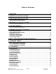
Table of Contents 1. FEATURES ...................................................................................... 6 2. ELECTRICAL SPECIFICATIONS ....................................................... 6 3. OPERATING SPECIFICATIONS ....................................................... 7 Communication Specifications ........................................................................... 7 4. MECHANICAL SPECIFICATIONS .....................................................
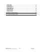
SB Step Back ................................................................................................... SD Save Data .................................................................................................. SF Step Forward .............................................................................................. SM Stop Motion ............................................................................................... SR Step Resolution ..............................................
1. FEATURES • • • • • • • • • • Single Axis Driver/Indexer for Bipolar Step Motors Operates from +15 to 30 VDC Phase currents between 0.2 to 2.5 Amp Peak Automatic Motor Holding Current reduction available from 0.2 to 2.
3. OPERATING SPECIFICATIONS Maximum Step Frequency 15 kHz Operating Temperature Automatic Motor Holding Current reduction available from 0.2 to 2.5 Amps Logic Timing Minimum Step Pulse Width Minimum Step Low Time Maximum Power-Down Recovery Time 33 microseconds 33 microseconds 20 milliseconds Communication Specifications Address bytes in the RS485 commands allow multiple units (26 units max) to be controlled from a single host port.
5. PIN ASSIGNMENTS A 12 pin pluggable terminal strip connector JP1 provides power and the step and direction control functions for the module. All of these signals are optically isolated. Open-collector drives are required to provide pulses for Step, levels for Direction Disable, and Zero Set.
6. CONNECTION SPECIFICATIONS To begin using the R101 Driver/Indexer we must first connect a power supply. Then a few basic settings must be made to setup the R101 for basic operation. These settings are typically made using Windows HyperTerminal. The R101 is connected to a PC by using the RS485 Converter Card connected to JP3 (See Section 5 for Pin Assignments) with 15-30 VDC being applied to the board. The converter card allows the R101 to connect to the PC via a standard serial port.
Example Setting the Run Current (RI) to 1500mA (1.5A) #ARI1500 *ARI1500 //Sent Command //Received Reply Setting the Current There are two current settings on the R101. 1. Run Current (RI) – The peak current that the motor will be run at while in motion. 2. Hold Current (HI) – The current that the motor will receive when idle. *The default board address of ‘A’ is used in all examples, please see “MA” command for more detail on addresses. Examples: To set Run Current to 2000mA (2.
Connecting the Motor WARNING! Make sure the power is OFF when connecting or disconnecting motors from the R101. Damage will occur if the power is being supplied. Please refer to your motor documentation for wiring color code. Connect the corresponding Phase from the motor to the proper pin on the R101. Using the R101 If using the R101 in Step/Direction mode, please proceed to Section 8 – Basic Step and Direction Operation.
8. BASIC STEP AND DIRECTION OPERATION The four control signals Step, Direction, Disable, and Zero Set are optically isolated, with a common positive connection (usually 5 VDC). The common positive connection (Pin 1) is typically 5 VDC. Each of the inputs is set to TRUE by supplying a signal level 5V below the common positive connection powering the optical isolators. The input is set FALSE by putting the signal within 0.5 VDC below the common positive value.
9.
10. COMMANDS (Page per Command Listing) Command Format is: #
Response Format is: * stand for "Carriage Return" and "Line Feed" respectively. These are NOT characters to be typed in. For direct keyboard users, these values are executed when the "Return" key is pressed. For programmers, a "Carriage Return" and "Line Feed" (also known as a "New Line") command needs to be executed after each command.AC Acceleration Initial Acceleration (1 to 32767 steps/Sec ^2 *10^-2) Command or Query. Used to shape the acceleration and deceleration ramps of position moves, and the rate of velocity change for velocity moves. Does not affect any of the basic step and direction move operations Command Example #AAC10000 Sets acceleration to 100 PPS^2. Default value is 50 RMS Technologies R101 Single Axis Driver/Indexer Manual Page 15 Version 1.
AP Absolute Position Absolute Position +/–2,147,483,646 Command Only Used to make an absolute position move. Command Example #AAP1000 Moves to absolute position of 1000. RMS Technologies R101 Single Axis Driver/Indexer Manual Page 16 Version 1.
CP Current Position Current Position +/–2,147,483,646 Command or Query. Returns the absolute position of the axis if no value is passed. Valid after power cycles if a Save Data Command is issued before power down. Can be used to set current position value. The units are steps at the current step resolution. (Value becomes invalid with step resolution changes.) The absolute position scale is set to zero by the Zero Position command (ZP) or the execution of a Home Axis (HA) command.
CV Current Velocity Query Only +/- 15,000 Only valid when a position move (PM) or velocity move (VM) is in progress. Otherwise returns zero. Command Example #ACV RMS Technologies R101 Single Axis Driver/Indexer Manual Page 18 Version 1.
FR Firmware Revision Query Only Returns product and firmware revision numbers. Command Example #AFR Reply *AFR101100 //R101 firmware revision 1.00 RMS Technologies R101 Single Axis Driver/Indexer Manual Page 19 Version 1.
HA Home Axis Command Only Reverse(1) or Forward(0). Causes the motor to move at the preset Start Velocity (SV) in the direction set by the command value. Motion stops by either the ‘Other’ input (JP1-10) being set TRUE, or the entry of a Stop Motion (SM) command. Forward is defined as the direction the motor turns when the ‘Direction’ input (JP1-3) is set FALSE, or there is no connection to this input. Command Example #AHA1 Motor turns in the Reverse direction.
HI Hold Current Command or Query 0 to 2500 Reads or sets the motor Holding Current. The value is the current in Amps times ten. Command Example #AHI300 Sets the Hold Current to 300mA (0.3 Amp). Default value is 300 RMS Technologies R101 Single Axis Driver/Indexer Manual Page 21 Version 1.
HT Hold Timeout Command or Query 100 to 5,000. Reads or sets the time interval in milliseconds after any motor movement, before the motor current is changed from Run Current to Hold Current Command Example #AHT100 Sets the Hold Timeout to 100 mS. Default value is 5000 RMS Technologies R101 Single Axis Driver/Indexer Manual Page 22 Version 1.
LD Load Defaults Command Only Loads all of the unit Default parameter values. A save Data (SD) command must be issued to have these values retained during a power cycle. Command Example #ALD Loads all default values. Default values are: My Address Absolute Position Step Resolution Run Current Hold Current Hold Timeout Velocity Limit Minimum Velocity Start Velocity 65 (A) 0 8 10 (1.0A) 3 (0.3A) 5,000 15,000 250 1,000 RMS Technologies R101 Single Axis Driver/Indexer Manual Page 23 Version 1.
MA My Address Command or Query 65 to 90. Reads or sets the unit address. The value read or entered is the decimal value of the ASCII character designated as the unit address. (65 = ‘A’ and 90 = ‘Z’) The change to a new address is immediate, in that the command response will use the new address Command Example #AMA88 Sets the unit address to 88 (‘X’).
MS Move Status Query Only. Reads Motion Status. Returns 0 for No Motion, 1 for Position Move, and 2 for Velocity Move. Command Example #AMS Queries the current status RMS Technologies R101 Single Axis Driver/Indexer Manual Page 25 Version 1.
MV Minimum Velocity Command or Query 250 to 15,000. Reads or sets the minimum velocity for both Position and Velocity command moves The units are steps (at the current Step Resolution) per second Command Example #AMV500 Sets Minimum Velocity to 500 SPS Default value is 250 NOTE: Since the R101 follows a trapezoidal motion profile, the minimum velocity must be less than the Velocity Limit. The R101 will accelerate from MV to VL then decelerate down to MV.
PF Percent Fast Decay Command or Query 0, 1, or 2. Allows the Damping Mode of the driver IC to be set. 0 = Fast Decay 1 = Mixed Mode 2 = Slow Decay The optimum setting will vary with motor inductance and step rate; however the default ‘Mixed Mode’ setting will work well with almost all motors. Command Example #APF1 Sets Mixed Mode Damping. Default value is 1 RMS Technologies R101 Single Axis Driver/Indexer Manual Page 27 Version 1.
PM Position Move Command Only +/-2,147,483,646 Causes a ‘Relative Motion’ Position Move, using an approximately trapezoidal profile. The initial velocity is defined by ‘Start Velocity’ (SV), the profile ramp is defined by ‘Acceleration’ (AC), and the ‘Constant Velocity’ step rate by ‘Velocity Limit’ (VL). ‘Minimum Velocity’ (MV) is used to ensure that the deceleration ramp does not set velocity to zero before the target position is reached.
RI Run Current Command or Query 200 to 2500. Sets the motor Phase Current for any form of motion in 100mA increments. 200 = 200mA (0.2 Amp) 2500 = 2500mA (2.5 Amp) The set ‘Run Current’ is maintained for a time set by ‘Hold Timeout’ (HT) before dropping to the current set by ‘Hold Current’ (HI) Command Example #ARI1000 Sets the run current to 1000mA (1 Amp). Default value is 1000 RMS Technologies R101 Single Axis Driver/Indexer Manual Page 29 Version 1.
RS Read Switches Query Only Reads the TRUE (1) or FALSE (0) state of the four optically coupled inputs, combined into a single four-bit value. This command is used to check the correct operation of this interface. The value order of the inputs is ‘Zero Set’, ‘Disable’, ‘Direction’, and ‘Step’. in descending order. ‘Zero Set’ has the value 8 ‘Direction’ has the value 4 ‘Disable’ has the value 2 ‘Step’ has the value 1 (1000) (0100) (0010) (0001) Command Example #ARS Reads the switch inputs.
SB Step Back Command Only Makes a single step move at the current step resolution Forward is defined as the direction the motor moves with the ‘Direction’ input in the FALSE state, or with no connection. Backwards is thus the direction the motor moves when the ‘Direction’ input is in the energized or TRUE state. Command Example #ASB Moves one step back. RMS Technologies R101 Single Axis Driver/Indexer Manual Page 31 Version 1.
SD Save Data Command Only This command causes a set of parameter values to be written to non-volatile memory. On power up the last set of values written are set to be the parameter initial values. The parameters whose values are thus saved are: My Address Absolute Position Velocity Limit Minimum Velocity Start Velocity Acceleration Hold Timeout Step Resolution Run Current Hold Current Percent Fast Decay Command Example #ASD Saves Data.
SF Step Forward Command Only Makes a single step move at the current step resolution Forward is defined as the direction the motor moves with the ‘Direction’ input in the FALSE state, or with no connection. Backwards is thus the direction the motor moves when the ‘Direction’ input is in the energized or TRUE state. Command Example #ASF Moves one step forward. RMS Technologies R101 Single Axis Driver/Indexer Manual Page 33 Version 1.
SM Stop Motion Command Only This command can be used to affect an end to any Position Move or Velocity Move in progress. It has no effect on motion produced by the Step and Direction inputs. Command Example #ASM Stops any Position or Velocity move in progress. RMS Technologies R101 Single Axis Driver/Indexer Manual Page 34 Version 1.
SR Step Resolution Command or Query 1, 2, 4, or 8 Reads or sets the current step resolution Allowed values are: 8 4 2 1 for for for for 8x microstepping 4x microstepping 2x microstepping Full step Command Example #ASR4 Sets the step resolution to 4x microstepping. Default value is 8 RMS Technologies R101 Single Axis Driver/Indexer Manual Page 35 Version 1.
SV Start Velocity Command or Query 250 to 15,000 Reads or sets the velocity used for the first step in a position move. Value based on motor performance. Command Example #ASV500 Sets Start Velocity to 500 PPS. Default value is 1,000 RMS Technologies R101 Single Axis Driver/Indexer Manual Page 36 Version 1.
VL Velocity Limit Command or Query 250 to 15,000 Reads or sets the velocity used for the constant velocity portion of a position move. Command Example #AVL5000 Sets the velocity limit to 5000 PPS. Default value is 15,000 NOTE: Since the R101 follows a trapezoidal motion profile, the minimum velocity must be less than the Velocity Limit. The R101 will accelerate from MV to VL then decelerate down to MV. (#AMV < #AVL) RMS Technologies R101 Single Axis Driver/Indexer Manual Page 37 Version 1.
VM Velocity Move Command Only +/- 250 to 15,000, or 0 The sign of the value determines the direction (positive for forward, and negative for backward) in which the velocity move is made. The value sets the step rate in steps per second at the current step resolution. Velocity cannot exceed Velocity Limit The move begins at the set ‘Minimum Velocity’ (MV), with the speed ramping to the command velocity at the rate set by ‘Acceleration’ (AC).
ZP Zero Position Command Only Sets the current value of the Absolute Position scale to zero Command Example #AZP Sets Absolute Position to zero. RMS Technologies R101 Single Axis Driver/Indexer Manual Page 39 Version 1.
11. RS485 Communication 1. The Interface The EIA specification RS485 defines an integrated circuit that is to be used to connect up to 32 nodes to a two-wire party line bus that does not exceed 4,000 ft. in length, and for use with data rates up to 10M Baud. The two-wire bus must be terminated at one-end for short wire runs and at both ends if the runs exceed 20 ft. One of the two wires must be biased positive with respect to the other by approximately 700 millivolts.
A one character time interval has to be allowed between outgoing and incoming messages, to allow for line turn-around (Switching between Transmit and Receive). At 57,600 baud, one character with 11 bits (one start, eight data, and two stop bits) transmits in 191 µS. 4. Validation Commands are validated by comparing the content of the reply with the content of the command message on a character by character basis.
12. Troubleshooting & FAQ R101 is not functioning correctly Try putting the R101 into TEST mode by placing a jumper on Pins 9 & 10 of JP2. The Motor should twitch back and forth slightly. RMS Technologies R101 Single Axis Driver/Indexer Manual Page 42 Version 1.
14. Appendix B: PF Value For applications requiring ultimate smoothness of motion and extreme accuracy, the R3101 driver can be programmed via RS485 to change the Percent Fast Decay rate, or, the PF value. The Percent Fast Decay default is 1, or a mixed mode decay. Mixed mode is a damping technique done to the driver IC.
• • • PF value 2 Slow speeds Bad waveform • • • PF value 1 Fast speeds Bad waveform RMS Technologies R101 Single Axis Driver/Indexer Manual Page 44 Version 1.