
User guide


RMS Technologies Page 9 Version 1.04
IMD17/IMDE17 10/1/2007
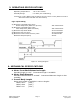
5. CONNECTORS
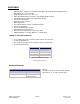
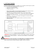
A DB-9 female connector cable receives power and provides the control connections for the
IMD17 Unit. Active signals are optically isolated. An open-collector drive is required to provide
pulses for Step, levels for Direction and Disable/Enable.
PIN # COLOR
(#26 AWG Lead)
FUNCTION DESCRIPTION
1 Red +V Motor Supply Voltage. +12 to +24 VDC
2 Black SR1 Input Step Resolution 1. Pins 2 & 3 are used to
preset the step resolution by selective
contact to ground (Pin 7)
3 Brown SR2 Input Step Resolution 2. Pins 2 & 3 are used to
preset the step resolution by selective
contact to ground (Pin 7)
4 Black/White Enable/Disable
Input
This input is used to enable/disable the
output of the driver
5 Orange Direction Input This input is used to change the rotation
direction of the motor
6 Green Power Ground The ground or return of power supply
connects here.
7 White Logic Ground Used to ground to the logic functions (i.e.
step resolution)
8 Blue Opto Supply +5 VDC input used to supply power to the
isolated logic inputs**
9 Yellow Step Clock Connects to the open-collector drive.
Table 3: Pin Assignments
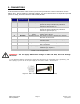
WARNING! - Do not apply differential voltage on SR1 and SR2, this will damage
the driver.
**
The Resistors shall be connected in series with each Input: Pin 4 (Disable), Pin 5 (Direction), and
Pin 9 (Step) if you are to use an opto supply of more than +5VDC. See Section 7.
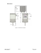
Figure 3: DB-9 Female Cable Connector (Rear View)