
User guide

RMS Technologies Page 11 Version 1.04
IMD17/IMDE17 10/1/2007
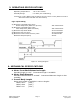
ALTERNATIVE STEP RESOLUTION CONNECTION
It is possible to change the microstepping resolution by using the signal from the
controller.
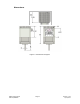
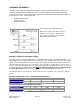
Figure 5: Alternative Step Resolution Connection
By sending a high signal to Pin 2 and/or Pin 3, the connection between these pins
will be effectively closed with Pin 7. This will change the microstepping resolution.
Please refer to the Table 3 for Step Resolution Settings.
PLEASE NOTE: The microstepping resolution should not be changed on the fly, loss of step
may occur.
7. CONFIGURING AND CONTROLLING THE IMD17
SIGNAL CONTROL SPECIFICATIONS
Step Resolution SR1
(Black)
SR2
(Brown)
Full Close Close
Half Close Open
1/4 Open Close
1/8 Open Open
Table 4: Step Resolution Settings
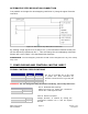
SR1 (Pin 2) and SR2 (Pin 3) are used
to preset the step resolution by
selective contact closure to ground (Pin
7).
WARNING! Do not change the Step Resolution on the fly, loss of step will occur.
Enable/Disable
Enable Open
Disable Close
Table
5: Enable/Disable Settings
Disable the Driver by closing the connection
between Pin 4 and Signal Ground.
Direction
Clockwise Close
Counterclockwise Open
Table 6: Direction Settings
Change direction of rotation by closing the
connections between Pin 5 and the Signal
Ground.