
User guide


RMS Technologies Page 10 Version 1.04
IMD17/IMDE17 10/1/2007
6. GETTING STARTED
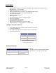
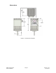
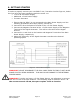
In order to properly connect your new IMD17 Unit, first take a look at Figure 4, below.
Here’s a list of the parts needed to make the motor run:
• +12 to 24 Volt Power Supply
• Additional +5 Volt Power Supply
• Function Generator
1. Ensure that the IMD17 is not connected to the Main Power Supply until the
following procedures have been properly carried out.
2. Connect Pin 8 to the Positive Terminal of the +5 VDC Power Supply.
3. Connect the Negative Terminal of the +5 VDC Power Supply to the Negative
Terminal of the Signal Generator. This will be referred to as the Signal
Ground.
4. Connect Pin 1 and Pin 6 to the Positive and Negative Terminals of the Main
Power Supply, respectively.
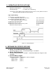
5. Adjust the Frequency of the Signal Generator to achieve the desired
operating speed.
Figure 4: Connections Diagram
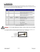
WARNING! DO NOT DISCONNECT THE DB-9 CABLE FROM THE IMD17 UNIT WHILE
POWER IS STILL BEING SUPPLIED. THIS MAY CAUSE DAMAGE TO THE INTERNAL
DRIVER BOARD.
WARNING! If you do not have a +5 VDC Power Source, use a Resistor in series to
limit the current of the opto isolators. See following page for Resistor values. If
the current exceeds 10 mA, the opto couplers cease to function.