Configuration Module User Manual Version 1.00 RMS Technologies. 2533 N. Carson St. #4698 Carson City NV 89706 877-301-3609 www.rmsmotion.com . sales@rmsmotion.com . support@rmsmotion.com Configuration Module (ACC-02) Page 1 Version 1.
Thank you for purchasing the configuration module. This product is warranted to be free of manufacturing defects for one (1) year from the date of purchase. DISCLAIMER The information provided in this document is believed to be reliable. However, no responsibility is assumed for any possible inaccuracies or omissions. Specifications are subject to change without notice.
Configuration Module User Manual Used with Products: IMD23/IMDE23 Version: 1.00 Date: 8/31/2007 Version History Version Date Description of Changes 1.00 8/31/2007 First User Manual Configuration Module (ACC-02) Page 3 Version 1.
Table of Contents PLEASE READ BEFORE USING ...................... ERROR! BOOKMARK NOT DEFINED. DISCLAIMER ............................................................................................................................ 2 TABLE OF CONTENTS .......................................................................................................... 4 1 FEATURES..............................................................................................................................
1 Features • • • • • • Dipswitches are used for simplicity in changing the following settings: o Step resolution from 2x to 256x microstepping o Run Current o Hold Current choices of 0%, 25%, 50%, and 100% of the run current o Disable Power choice for holding in place or no power when disabling the unit o Step Sensing choice of reading from the rising or falling edge of each step pulse input o Direction Sensing choice of reading from the rising or falling edge of the pulse for changing direction of rotati
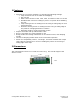
3 How To Use The configuration module currently is used with the IMD23 or IMDE23 unit. Soon, other units can be used with this as well. 1. Power Off the power supply and Opto Supply and disconnect or power off any step, direction, and disable/enable signals. If using the internal opto supply, disconnect it. 2. Set all the DIP switches on the Config Module to the required positions 3. Connect the Config Module to the unit being set, by using the provided cable. 4.
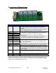
4 Functions of Dipswitches Switch SW1-1 Abbreviation Disable PWR SW1-2 SW1-3 SW1-4 SW2-1 SW2-2 SW2-3 SW2-4 SW3-1 SW3-2 Step Res 0 Step Res 1 Step Res 2 Run Cur 0 Run Cur 1 Run Cur 2 Run Cur 3 Hold Cur 0 Hold Cur 1 SW3-3 SW3-4 SW4-1 Damping 0 Damping 1 Step Sense SW4-2 Dir Sense SW4-3 SW4-4 Mode 0 Mode 1 Description of Function Disable Power On: Motor powers off when disabling unit and step is inhibited Off: Motor receives current from the last step pulse input prior to disabling the unit and step
Disable Power When a driver is disabled by pulling the enable/disable pin low, the motor will stop movement and remember the location of the current waveform, such that, when enabling the unit, the step sequence is not lost and the waveform continues on. The disable power function has two options: ON: The motor receives no current, and is therefore considered completely disabled OFF: The motor receives the current supplied to it at the time it is disabled, and will hold in place.
Hold Current The motor changes from run current to hold current 2.25 seconds after the motor stops stepping. Four percentage selections are available for hold current. It is a percentage of the selected run current. HOLD CUR 0 OFF ON OFF ON HOLD CUR 1 OFF OFF ON ON Holding % 0% 25% 50% 100% Damping A total of four damping modes are provided in order to aid in resonance and vibration within the motor. This is also known as mixed decay. The current waveform is dampened to create a smoother motion profile.
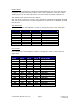
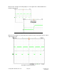
Notice in this example, the falling edge is a clear signal and a definite difference between high to low. Example of a bad rising edge waveform Below is an example of a good step pulse waveform where sensing the step on either edge would be fine: Example of a good waveform Configuration Module (ACC-02) Page 10 Version 1.
Direction Sense This is similar to the “step sense” feature where the direction of rotation can change upon seeing the rising edge of a signal or the falling edge of a signal. The switch has two options: ON: Changes direction on a rising edge signal (looks for a low to high transition) OFF: Changes direction on a falling edge signal (looks for a high to low transition) Configuration Module (ACC-02) Page 11 Version 1.