IMD23/IMDE23 Integrated NEMA 23 Motor and Drive With Encoder option Plus with New Configuration Module IMD ACC-02Configuration Module (sold separately) User Manual And Commands Guide Version 1.10 RMS Technologies 2533 N. Carson St. #4698, Carson City, NV 89706-0147 1-877-301-3609 www.rmsmotion.com sales@rmsmotion.
Thank you for purchasing the IMD23 or IMDE23 Integrated Motor and Driver. This product is warranted to be free of manufacturing defects for one (1) year from the date of purchase. PLEASE READ BEFORE USING Before you start, you must have a suitable step motor, a DC power supply suitable for the motor. The power supply voltage must be between 4 times and 20 times the motor's rated voltage. DISCLAIMER The information provided in this document is believed to be reliable.
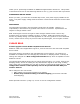
IMD/IMDE23 User Manual Product: Version: Date: IMD23 and IMDE23 1.10 12/3/2007 Version History Version Date 1.05 6/5/2006 1.06 6/7/2007 1.07 8/31/2007 1.08 10/26/2007 1.09 11/5/2007 1.10 12/3/2007 RMS Technologies IMD23/23DE Manual Description of Changes Standardized user manual & updated description of configuration module & duty cycle Added configuration module info and RoHS compliant board info. Updated opto-isolation info.
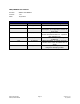
Table of Contents 1 FEATURES ....................................................................................................................................................... 5 POLE DAMPING TECHNOLOGY™ ....................................................................................................... 5 IMD23E – ENCODER FEATURES......................................................................................................... 5 DEFAULT SETTINGS ..............................................
1 FEATURES • • • • • • • • • • • NEMA Size 23, 2 Phase, 1.8° Bipolar Step Motor w/ Built-In Microstepping Driver Operates from +12 to 48 VDC with certain currents* Selectable phase currents from 0.3 to 3.
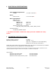
2 ELECTRICAL SPECIFICATIONS Power Supply Requirements Voltage +12 VDC to 48 VDC* Driver Peak Current: 0.3 to 3.0 Amps* Motor Specifications NEMA Size 23 Holding Torque: IMD23-S-XX 100 oz-in IMD23-M-XX 182 oz-in IMD23-L-XX 294 oz-in Steps per Revolution (1.
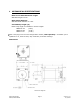
4 MECHANICAL SPECIFICATIONS Motor Front Shaft Extension Length Standard length is 0.81”. Motor Shaft Diameter Standard shaft diameter is 0.25”. Overall Body Length (A) Motor body length is available in various lengths IMD23-S-XX IMD23-M-XX IMD23-L-XX (2.52”) (2.96”) (3.89”) Note: This plug is for the new configuration module, sold separately. It enables you to update the run, hold currents, step resolution, and other settings.
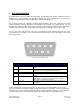
5 PIN ASSIGNMENTS A female DB-9 connector cable receives power and provides the control connections for the IMD23 unit. Active signals are optically isolated. An open collector drive is required to provide pulses for Step, levels for Direction, and Disable/Enable. All of these signals are optically isolated. Open-collector drives are required to provide pulses for Step, levels for Direction, and Disable.
6 CONNECTION SPECIFICATIONS In order to properly connect your new IMD23 unit, examine the figure below. Connecting the IMD23 to a Controller List of components needed to spin the motor: • • • +12 to 48 VDC Power Supply Additional +5 VDC Volt Power Supply Signal Generator 1. Ensure that the IMD23 is not connected to the Main Power Supply until the following procedures have been properly carried out. 2. Connect Pin 8 to the Positive Terminal of the +5 VDC Power Supply. 3.
Pin 9 (Direction): To switch the direction of motor rotation; connect Pin 9 with Pin 2 & 7, Power Ground. An open or closed connection to Power Ground will change the direction. Pin 3: This is the internal +5VDC. Use this for testing purposes or if optical isolation of the I/O’s is not desired. Pin 5 (Disable): To enable and disable the drive, connect Pin 5 with Pin 2 & 7, Power Ground. An open or closed connection to Power Ground will enable and disable the drive, respectively.
Example Connection Schematic – Connecting to a Signal Generator Connecting the Power The IMD23 requires a supply voltage of +12-48 VDC. First, connect the positive end of the power supply to Power (Pins 1 & 6), and then connect the negative of the power supply to the Ground (Pins 2 & 7) on the IMD23. WARNING! Be careful not to reverse the polarity from the power supply to the driver. Reversing the connection will destroy your driver and void the warranty.
7 Configuring The Settings PLEASE READ As of August 31, 2007, the IMD23 and DE23 units have new RoHS compliant boards along with a few upgrades.
Configuring Settings using Configuration Module (for new RoHS products) Default Settings of the IMD23 or DE Direction of rotation Counterclockwise Disable Power On – motor power is disabled when disabling unit Step Resolution 8x step (3200 steps/rev) Run Current Motor’s rated current or up to 3 Amps Peak if motor is rated for 3 or higher.
3. Connect the Config Module to the IMD23 or DE using the provided cable. Connector is located on bottom of the motor unit shown where the star is here: 4. Only power on the MAIN Power Supply. Do not power the Opto Supply and no function generator or step pulses either. Module LED should not light up. 5. Press and HOLD the black button on the Config Module (S3). When Black button is pressed and held the GREEN LED on the Config Module should light. This indicates that the settings have been stored.
*Note: Dipswitches are switched “ON” when switches are towards the RIGHT when looking at the configuration module and reading the silk screen descriptions upright. There is also a marking labeled as “ON”. Disable Power When a driver is disabled by pulling the enable/disable pin low, the motor will stop movement and remember the location of the current waveform, such that, when enabling the unit, the step sequence is not lost and the waveform continues on.
Hold Current The motor changes from run current to hold current 2.25 seconds after the motor stops stepping. Four percentage selections are available for hold current. It is a percentage of the selected run current. HOLD CUR 0 OFF ON OFF ON HOLD CUR 1 OFF OFF ON ON Holding % 0% 25% 50% 100% Damping A total of four damping modes are provided in order to aid in resonance and vibration within the motor. This is also known as mixed decay. The current waveform is dampened to create a smoother motion profile.
• • • PF value 2 Slow speeds Bad waveform • • • PF value 1 Fast speeds Bad waveform Step Sense This feature allows for more compatibility with controllers and PLC’s. The IMD23 driver board receives step pulses from a pulse train, normally a TTL signal, sensing each pulse, one by one. The “step sense” feature can choose where to sense each pulse: on the rising edge of the step or the falling edge (also known as the positive or negative edge).
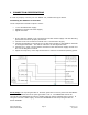
ON: Reads the step signal on the rising edge or positive edge OFF: Reads the step signal on the falling edge or negative edge Below depicts a step pulse train waveform where the rising edge is more of a curve. If the IMD23 and configuration module is set to read this type of signal on the rising edge, inaccurate steps and unsmooth motion may occur. It is best to switch the step sensing to the negative edge, or falling edge.
Example of a good waveform Direction Sense: This is similar to the “step sense” feature where the direction of rotation can change upon seeing the rising edge of a signal or the falling edge of a signal. The switch has two options: ON: Changes direction on a rising edge signal (looks for a low to high transition) OFF: Changes direction on a falling edge signal (looks for a high to low transition) RMS Technologies IMD23/23DE Manual Page 19 Version 1.
BASIC STEP AND DIRECTION OPERATION The three control signals Step, Direction, and Disable, are optically isolated, with a common positive connection (usually 5 VDC). The common positive connection (Pin 8) is typically 5 VDC. Each of the inputs is set to TRUE by supplying a signal level 5V below the common positive connection powering the optical isolators. The input is set FALSE by putting the signal within 0.5 VDC below the common positive value.
8 TROUBLESHOOTING The motor is not functioning correctly Check if power is being supplied to the unit. If the shaft of the motor is hard to turn, power is on. Next, check if the signal generator is supplying pulses correctly. Verify that the 5V is being supplied to the opto couples either via a separate power source or the internal 5V from Pin 3. The motor is not moving Verify that the 5V is being supplied to Pin 8.
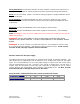
9 Appendix A Recommended Cable Configurations: DC Supply to Driver Cable length, wire gauge and power conditioning devices play a major role in the performance of your RMS Technologies Driver and Motor. NOTE: The length of the DC power supply cable to the Driver should not exceed 50 feet. Example A demonstrates the recommended cable configuration for DC power supply cabling under 50 feet long.
NOTE: These recommendations will provide optimal protection against EMI and RFI. The actual cable type, wire gauge, shield type and filtering devices used are dependent on the customer’s application and system.