IMD34 / IMDE34 Integrated NEMA 34 Motor and Drive With Encoder option User Manual And Commands Guide Version 1.00 RMS Technologies 2533 N. Carson St. #4698, Carson City, NV 89706-0147 www.rmsmotion.com . sales@rmsmotion.com .
Thank you for purchasing the IMD34 or IMDE34 Integrated Motor and Driver. This product is warranted to be free of manufacturing defects for one (1) year from the date of purchase. PLEASE READ BEFORE USING Before you start, you must have a DC power supply suitable for the motor. It is recommended to use a power supply voltage between 4 times and 20 times the motor's rated voltage. (Rated voltage can be calculated by multiplying the motor’s rated current and the motor’s resistance value).
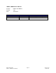
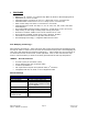
IMD34/IMDE34 User Manual Product: Version: Date: IMD34 and IMDE34 1.00 4/28/2009 Version History Version Date Description of Changes 1.00 4/28/2009 New Manual RMS Technologies IMD34 / IMDE34 User Manual Page 3 Version 1.
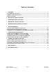
Table of Contents 1 FEATURES .........................................................................................................................................................5 POLE DAMPING TECHNOLOGY™ ................................................................................... 5 IMDE34 – ENCODER FEATURES.................................................................................. 5 DEFAULT SETTINGS ........................................................................................
1 FEATURES • • • • • • • • • • • • NEMA Size 34, 2 Phase, 1.8° Bipolar Step Motor w/ Built-In Microstepping Driver Operates from +24 to 75 VDC Selectable phase currents from 0.5 to 7.0 Amp Peak (in 0.1 A increments) Selectable hold currents from 0.0 to 7.0 Amps (in 0.1 A increments) Hold current delay time from 0.5 seconds to 6.
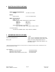
2 ELECTRICAL SPECIFICATIONS Power Supply Requirements Voltage +24 VDC to 75 VDC Driver Peak Current: 0.5 to 7.0 Amps Peak Motor Specifications NEMA Size 34 Holding Torque when using motor’s rated current: IMD34-S 435 oz-in IMD34-M 830 oz-in IMD34-L 1288 oz-in Steps per Revolution (1.
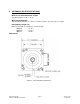
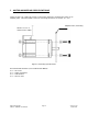
4 MECHANICAL SPECIFICATIONS Motor Front Shaft Extension Length Standard length is 1.46 +/- 0.02”. Motor Shaft Diameter Standard shaft diameter is 0.5000” +0.0000/-0.0005, with two flats, 90° apart. Overall Body Length (A) Motor body length is available in various lengths IMD34-S IMD34-M IMD34-L Dimensions (4.44”) (5.62”) (6.80”) Figure 1: Front Mounting dimensions RMS Technologies IMD34 / IMDE34 User Manual Page 7 Version 1.
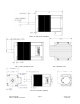
Figure 2: Side view of IMD34 Fig 3: Side connection view Fig 4: Bottom view Fig 5: E3 encoder drawing RMS Technologies IMD34 / IMDE34 User Manual Page 8 Version 1.
5 MOTOR MOUNTING SPECIFICATIONS There are four (4) 0.258” thru holes on the motor flange for mounting the motor to an adapter plate. Recommended screws for mounting the motor are 0.250” or ¼-20. Adapter Plate / Mounting Allow 1.0” to 1.5” clearance for cables Figure 6: Mounting Specifications Recommended hardware (not included with IMD34) 4 x ¼-20 screw 4 x ¼” Split lockwasher 4 x ¼” Flat washer 4 x ¼-20 lock nuts RMS Technologies IMD34 / IMDE34 User Manual Page 9 Version 1.
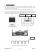
6 PIN ASSIGNMENTS A female 12-Pin connector cable provides the control connections for the IMD34 unit. Active signals are optically isolated. An open collector drive is required to provide pulses for Step, levels for Direction, and Disable/Enable. A separate 2-Pin connector needs to receive main power between +24VDC to 75VDC. All of the signals are optically isolated.
Control Pinouts & Description (P2) Provides input to the IMD34 driver.
7 Configuring The Settings Connecting IMD34 to your PC via USB All units come with the following cables: - A 12-Pin cable for supplying step, direction, and other functions - A 2-Pin cable for main power If you purchased a USB485 Designer’s Kit (RMS p/n USBKIT-03), then you should have received the following items: - A 3-Pin to 3-Pin cable for communication (p/n 090-00202) - USB to RS485 converter card - A USB cable (6 feet long) If you purchased a RS232-485 Designer’s Kit (RMS p/n RS232KIT-03), then you
1. Download driver files for the USB485 converter card Go to www.rmsmotion.com and navigate to the USB485 converter card page by going to: Accessories USB to RS485 Converter card. Then click on “Download”, or simply scroll to the bottom of the page. Save the zip file called “USB485 Driver Files” and extract all files to your PC. 2. Connect the USB485 converter card to the IMD unit.
Fig 12: Connection of IMD motor to USB Card to PC Note the COM Port number that was assigned to the converter card device by rightclicking on “My Computer” and going to: Hardware Tab Device Manager Ports (COM & LPT) RMS Motion US485 Connecting the IMD34 to your PC via RS232 If you purchased a Designer’s Kit, then you should have received the following items: - RS485-to-RS232 converter card (Black gray cover, DB-9 on one end) - 3-Pin to IDC connector type of cable with flying lead wires (36 inches long
Connecting Power After downloading files for the USB485 converter card, connect main power to the IMD34. Using HyperTerminal To Set Motor Parameters Open a HyperTerminal connection by going to: All Programs Accessories Communications HyperTerminal 1. Settings Give your connection a name. It will then ask you to select the correct COM port. See note above this section to find the COM Port number. It should direct you to the properties of the connection.
Figure 16: ASCII settings RMS Technologies IMD34 / IMDE34 User Manual Page 16 Version 1.
2. Programming If programming in HyperTerminal, follow the syntax shown below: #[ADDRESS][COMMAND][VALUE] The following list contains the parameters with examples for HyperTerminal: Range Example Default Function value DR 0 or 1 #ADR1 0 Direction of Rotation. Changes direction of rotation. By default, motor will rotate CCW. FR n/a #AFR n/a Firmware Revision. Displays the existing firmware revision. HI 0 - 7000 #AHI5000 2500 Holding Current.
Example: #AFR #ASR256 #ARI5000 #ASD show the firmware version set the step resolution to 256 microstepping set the current to 5A peak Save data Using the GUI Software to Set Parameters: If using the GUI interface, simply download the executable from the IMD34 webpage in the download section. Unzip the file. Upon opening the Driver GUI, a screen shown above will pop up. Select the “IMD34/IMDE34” Product, and click “Open”.
Reads IMD34 board firmware version # and date. Reads back stored data 1 Loads default values Click “Set All” then “Save DATA” to store parameters 2 1 1. Set newly changed settings. 2.
Connect the positive terminal of your 5VDC supply to Pin 2, the opto input supply. The ground terminal of your supply should connect to the ground wire of the step pulse function generator. Users have an option to use the IMD34 internal 5VDC supply for ease of use. Connect pin 2 to pin 4 with a wire. By doing so, the system is no longer optically isolated. 3. Connect the direction pin The IMD34 unit will rotate counterclockwise if the direction pin is not connected to anything.
Connection Schematics Using external 5VDC supply for optos If using an external 5VDC supply, connect the positive (+) terminal to the IMD’s opto supply input, PIN 2. If using a signal generator, connect the 5VDC supply ground terminal to the negative line of the generator. Figure 20: Schematic with 5VDC Using IMD’s Internal 5VDC supply for optos If using the internal 5VDC supply, simply connect PIN 2 to PIN 4. Be sure to connect step pulse ground to the IMD’s Ground, PIN 9.
Using more than 5VDC for external supply for the optos If using more than 5VDC, connect resistors in series with the opto supply input, PIN 2. Use the table below to determine what resistor to use. Connect the 5VDC supply ground terminal to the IMD’s Ground, PIN 9. Figure 22: Schematic for more than 5VDC Resistor Values for the Opto Supply The optocouplers must be powered by an external power supply to maintain isolation.
Equation 1: Resistance Equations Equation 2: Wattage equations (Step down to 5VDC) 475 Ω 475Ω 475Ω Figure 23: Internal Schematic for Inputs RMS Technologies IMD34 / IMDE34 User Manual Page 23 Version 1.
9 Step Sensing The IMD34 is equipped with a parameter setting that allows users to change how it reads the step pulse input. Step Sensing This feature allows for more compatibility with controllers and PLC’s. The IMD34 driver board receives step pulses from a pulse train, normally a TTL signal, sensing each pulse, one by one. The “step sense” feature can choose where to sense each pulse: on the rising edge of the step or the falling edge (also known as the positive or negative edge).
Below is an example of a good step pulse waveform where sensing the step on either edge would be fine: Figure 25: Example of a good waveform RMS Technologies IMD34 / IMDE34 User Manual Page 25 Version 1.
10 GUI Error Codes This error occurs if you click on “Save DATA” and the board EEPROM does not respond. Check for main power Check for communication connection Check COM Port number This error occurs when you click on “Connect” and the COM Port does not respond. Check for main power Check for communication connection Check COM Port number This error occurs when you click on “Set” or “Set All” and the driver board is not receiving data from the PC.