
User Manual

R356 Controller & Driver Page 8 Version 1.06
RMS Technologies 2/17/2010
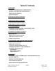
5. PIN ASSIGNMENTS
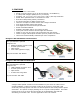
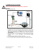
A DB-15 female connector cable comes with every R356 unit. It receives power and
provides the control connections for the R356 Unit. On the opposite end of the DB-
15 female connector cable, there is a 3 pin connector provided for the converter card
in order for the R356 to communicate with the PC. The four I/O wires are colored
Orange, Orange/White, White and Red/White. This will allow for options such as
solenoids, relays, opto isolators, LED’s and many other input and output connections.
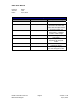
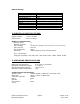
PIN # COLOR FUNCTION
I/O # or Function
1 Green Power Ground
2 Black 1A On/Off Output
3 White/Green Direction Input (see Appendix)
4 Yellow
+5VDC Input for Opto Isolated
STEP and DIR (see Appendix)
5 Orange Input
2/Jog2 Input
6 Yellow/White Internal Power for Opto Sensor
7 Orange/White Input (Opto Input)
3/Opto1 Input
8 Black/White RS485 A
9 Red +12V TO +40V POWER
10 Blue 1A ON/OFF Output
11 Blue/White Step Input (see Appendix)
12 Green/White Signal Ground
13 White Input
1/Jog1 Input
14 Red/White Input
4/Opto2 Input
15 Brown RS485 B
Table 2: Pin assignments
*Inputs are labeled 1, 2, 3 and 4 for programming the ‘Halt’, ‘Skip’, and special
mode ‘n’ commands.
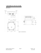
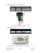
Figure 2: DB-15 Female Cable Connector (Rear View of R356 unit)
Cable 90-096 (connects with either RS485-232 or USB Card)