
User Manual


R356 Controller & Driver Page 17 Version 1.06
RMS Technologies 2/17/2010
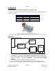
Changing the Address of the Controller
Use a screwdriver to turn the dial so the arrow points to the desired Address. Use
this number when programming commands. For example, /1P1000R
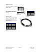
Figure 9: Address Dial
Note: New RoHS compliant boards have a Black dial instead of a Red one.
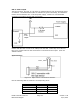
Connecting Accessories
If you have purchased the Designer’s Kit, there is a Red Push Button and an Optical
Sensor included. Follow the schematics below in order to properly assemble
accessory pieces.
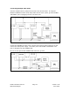
Push Button
Figure 10: Push Button Schematic
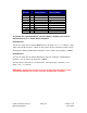
Pins 5, 7, 13 and 14 can all be used with push buttons. Below shows the
corresponding input numbers for these pins.
Input 1 Pin 13
Input 2 Pin 5
Input 3 Pin 7
Input 4 Pin 14
Table 7