R356 Controller with built-in 256x Microstepping Driver and encoder feedback for position correction User Manual Version 1.06 RMS Technologies 2533 N. Carson St.
Thank you for purchasing the R356 Controller with Microstepping Driver. This product is warranted to be free of manufacturing defects for one year from the date of purchase. PLEASE READ BEFORE USING Before you begin, ensure there is a suitable DC Power Supply. Do not disconnect the DB-15 cable while power is still being applied to the controller. This will damage the board. Under any circumstances, do not exceed +40 VDC. DISCLAIMER The information provided in this document is believed to be reliable.
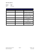
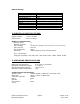
R356 User Manual Product: Version: Date: R356 1.06 2/17/2010 Version History Version Date Description of Changes 1.00 7/01/2008 New User Manual 1.01 4/3/2009 1.02 8/11/09 1.03 9/16/09 1.04 9/18/09 1.05 10/29/2009 1.06 2/17/2010 Added new RS485-232 converter card info and color code for opto sensor connection page 18. Added max surface temperature. Updated encoder cable image. Updated image for LED connection. Updated pinouts and Appendix for step/dir mode.
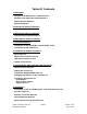
Table Of Contents 1. FEATURES 5 Designer’s Kit with RS232 communication 5 Designer’s Kit with USB communication 5 R356’s Encoder Option 5 Default Settings 6 2. ELECTRICAL SPECIFICATIONS 6 Digital I/O Specifications 6 3. OPERATING SPECIFICATIONS 6 Communication Specifications 6 4. MECHANICAL SPECIFICATIONS 7 5. PIN ASSIGNMENTS 8 Connecting to the new RoHS version RS232 card 9 Connecting to the USB card 9 6.
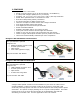
1. FEATURES • • • • • • • • • • • • • • • • Operates from +12V to 40V Single 2 wire bus linking up to 16 drive/controls ( on RS485 bus) 3.0 Amp Peak Chopper (PWM) Driver (2.
Default Settings Function (command) Description Running Current (m) 25% of 3.0 Amps Holding Current (h) 10% of the run current Step Resolution (j) 256x Top Velocity (V) 305175 pps (microsteps/sec) Acceleration (L) L=1000, 6103500 μsteps/sec2 Position 0 Microstep smoothness (o) 1500 Outputs (J) Both are turned off, J0, inputs 1 & 2 Baud Rate 9600 bps Table 1: Default Settings 2. ELECTRICAL SPECIFICATIONS Supply Voltage: Peak Current: +12 to +40 VDC 0.3 to 3.
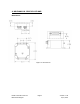
4. MECHANICAL SPECIFICATIONS Dimensions Figure 1: Dimensions R356 Controller & Driver RMS Technologies Page 7 Version 1.
5. PIN ASSIGNMENTS A DB-15 female connector cable comes with every R356 unit. It receives power and provides the control connections for the R356 Unit. On the opposite end of the DB15 female connector cable, there is a 3 pin connector provided for the converter card in order for the R356 to communicate with the PC. The four I/O wires are colored Orange, Orange/White, White and Red/White. This will allow for options such as solenoids, relays, opto isolators, LED’s and many other input and output connections.
Connecting to the new RoHS version RS232 card R356 pin# 8 1 15 R356 color Black/white *USB pin# 1 (RS485A) 2 (GND connect to Power Green Supply Ground) Brown 3 (RS485B) Table 3: Pinouts for using RS232 Pin 1 Figure 3: RS232 to RS485 converter card, p/n 083-00050 The RS232 card requires power (7-40VDC).
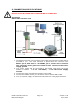
6. CONNECTION SPECIFICATIONS DO NOT PLUG IN POWER UNTIL EVERYTHING IS CONNECTED. Quick Start RS232-485 converter card Figure 5: Connection using RS232 1. The RS232 converter card connects to the R356 using the DB-15 cable that is provided to you. The 3-Pin connector is placed onto the converter card. R356’s pin 9, Red wire is +12-40VDC, pin 1, Green wire is Ground. The converter card’s green wire needs to also connect to the Power supply ground. 2.
USB-485 converter card Figure 6: Connection using USB 1. The USB converter card connects to the R356 using the DB-15 cable that is provided to you. The white 3-Pin connector is placed onto the converter card. 2. Connect the motor and optional encoder to the R356. 3. Your power supply will be connected to the R356 directly. The USB card is powered via the PC. R356’s pin 9, Red wire is +12-40VDC, pin 1, Green wire is Ground.
Mating Connectors The following cables are provided with the R356 unit: DB-15 cable: 4-Pin cable for step motor: One 4-pin cable is for the motor windings. The table to the right depicts the function Part # 90-018 Color Red Blue Green Black Table 5: Pin for Motor Function A+ Phase A- Phase B+ Phase B- Phase description Encoder cable: This is ideally for a US Digital E2, E5, or E3 encoder. One side plugs into the R356. The opposite side have flying leads for you to use.
7. CONFIGURING AND CONTROLLING THE R356 HyperTerminal Setup Please follow these steps in order to properly set up HyperTerminal: 1. Open a terminal from your PC by following these steps: Start Menu Æ Programs Æ Accessories Æ Communications Æ HyperTerminal 2. Assign a name for your New Connection 3. Determine the correct COM port # by right clicking on “My Computer” and selecting “Properties”. Select the “Hardware Tab” and click on “Device Manager”.
6. Turn on local echo by going to: File Æ Properties Æ Settings tab Æ ASCII Setup: Click on the box for “Echo Typed Characters Locally” and click on the box for “Send Line ends with line feeds”. Click “OK”. 7. Now you can type your commands Example command: /1A10000R • This will run unit #1 to the Absolute position 10000 • You can check the address of your driver by checking the dial at the top of the driver.
Percent 10% 20% 30% 40% 50% 60% 70% 80% 90% 100% = = = = = = = = = = Motor’s Current Driver’s Equivalent Rating (Amps) Current (Amps) 0.30 0.21 0.60 0.43 0.90 0.64 1.20 0.86 1.50 1.07 1.80 1.29 2.10 1.50 2.40 1.71 2.70 1.93 3.00 2.14 Table 5: Desired Current To achieve the equivalent Driver Current (Amps), multiply your motor’s rated current by 1.4. Follow these examples: Example One: You have a motor that is rated at 0.85 Amps, 0.85 Amps x 1.4 = ~1.2 Amps. Using Table 5 we would see that 1.
Connecting Multiple R356 Units Connect multiple units by using the Converter card, shown below. If using the RS232-to-RS485 converter card, daisy chain all four wires: power, ground, RS485+ and RS485- prior to plugging into the converter card. Figure 7: Connection using RS232 Converter Card If using the USB485 converter card, connect all the power and ground lines on the units to the main power supply. Then daisy chain the RS485+ and RS485- lines prior to plugging into the USB485 card.
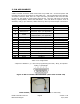
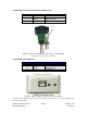
Changing the Address of the Controller Use a screwdriver to turn the dial so the arrow points to the desired Address. Use this number when programming commands. For example, /1P1000R Figure 9: Address Dial Note: New RoHS compliant boards have a Black dial instead of a Red one. Connecting Accessories If you have purchased the Designer’s Kit, there is a Red Push Button and an Optical Sensor included. Follow the schematics below in order to properly assemble accessory pieces.
LED or other output The two I/O lines, pins 2 & 10, can drive an external device such as solenoids, LED’s, or switches. The bidirectional I/O’s are switches to ground internally, and therefore need to be connected to the +V of the power supply. Below is a recommended connection for lighting an LED with 20 mAmps: Pin 2 or 10 output Upon entering command /1J0R, both pins 2 & 10 will output 1 Amps. The 1.2k ohm resistor will limit the current to 20 mAmps into the LED.
Table 8 8. APPENDIX Connecting to the non-RoHS RS232 card (with Red 4-Pin) If using the old non-RoHS converter card, here are the connection specifications for this converter card: R356 pin# 8 15 1 9 Table R356 color RS232 card pin# Black/white A (RS485A) Brown B (RS485B) Green - (GND) Red + (PWR) 9: Pinouts for using RS232 RS232 to RS485 converter card, p/n ACC-01 The RS232 card requires power (7-40VDC). Power is then sent to the motor via the Red 4-Pin connector.
How to connect with old cable: If you have a cable with a Red 4-Pin connector, simply cut off this connector, strip the wires and reconnect to a 3-Pin connector in the following manner: New 3-Pin cable Connect to Color/function Æ Connect to main power supply Æ Green (GND) Green (GND) Æ Brown RS485 B (+) Brown RS485 B (+) Æ Black/white RS485 A (-) Black/white RS485 A (-) Old 4-Pin cable Pin # Color/function Pin 1 Red (PWR) Pin # -- Pin 2 Pin 3 Pin 4 Pin 2 Pin 3 Pin 1 Encoder Usage The R356 can do closed
Third: Set the Overload Timeout Value: This is is the number of re-tries allowed under a stall condition: (default is 10) Fourth: Enable the Feedback mode: Zero the positions prior to enabling the feedback mode: /1z0R Issue /1n8R to enable the feedback mode. /1au10000R Overload Report Mode Overload report mode when enabled, will compare the encoder value to the commanded position at the end of a move and report an error if the two values do not match within the range given by “aC”.
Beginning at position 1, Phase A receives negative current, and Phase B receives positive current. Let’s assume it is at coordinate (-1, 1). PHASE B HALF- STEPPING Current Wave Form 8 7 1 PHASE A 2 6 PHASE A Current 5 3 4 Peak current (1.4 times Amps/Ph) 141% 100% time Average, or RMS Is only 1 Amp/Ph 0% 100% 141% POSITION 1 2 3 4 5 6 7 8 The position versus time graph just above, plots only the A Phase, following the eight different steps the motor will make.
Step and Direction Mode The R356 unit can be configured as a driver only by first connecting it to your PC and saving the special mode “n96” in program memory storage zero. 1. First connect to your PC and save n96 in storage zero: /1s0n96R 2. Next, connect the positive side of a TTL squarewave for step pulses to Pin 11 (Blue/white wire). 3. Connect a +5VDC supply to Pin 4 (Yellow wire). 4. Tie together the negative pin of the step pulse to the negative 5VDC supply. This becomes your signal ground. 5.