
Manual
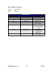
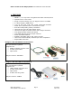
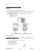
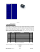
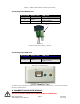
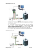

Figure 1: DB-9 Female Cable Connector (Rear View)
Connecting to the RS232 card
SP17C pin# SP17C color *USB pin#
4 Black/white 1 (RS485A)
6 Green
2 (GND connect to Power
Supply Ground)
3 Brown 3 (RS485B)
Table 4
Figure 2
The RS232 card requires power (7-40VDC)
Connecting to the USB card
SP17C pin# SP17C color *USB pin#
4 Black/white 1 (RS485A)
6 Green
2 (GND connect to Power
Supply Ground)
3 Brown 3 (RS485B)
Table 5
*Where Pin #1 is located here:
Figure 3
The USB converter card does not require power (it receives power from the PC). Power is still needed for
the IMC17 controller/driver.
6. CONNECTION SPECIFICATIONS
Quick Start
DO NOT PLUG IN POWER UNTIL EVERYTHING IS CONNECTED.
RMS Technologies Page 9 4/3/2009
IMC17/IMCE17 User Manual Rev 1.06
Pin 1