
Manual
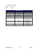

Pin Number
Function
1
Ground
2
Index
3
Channel A
4
+ 5 VDC
5
Channel B
Table 2:
Encoder Pinouts
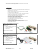
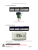
5. PIN ASSIGNMENTS
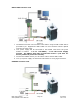
A DB-9 female connector cable receives power and provides the control connections
for the IMC17. The DB-9 cable has a 3 pin connector provided for the converter
card in order for the controller to communicate with the PC via an RS232 converter
card or USB card. Other wires allow the user to solder and program the switch push
button and the Opto Sensor, enabling several options. The I/O’s will allow for
options such as solenoids, relays, opto isolators, LED’s and many other input and
output connections. See Table3 below for details.
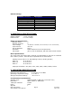
Pin # Color Function Input*
1 Red +V (Main Power In)
2 Black I/O 1
3 Brown RS485B (-)
4 Black/Whit
e
RS485A (+)
5 Orange Switch Closure to GND (IN) 4
6 Green GND (-V of main power in)
7 White Opto Sensor Phototransistor (IN) 3
8 Blue I/O 2
9 Yellow Opto Sensor LED (Power Out)
Table 3: Pin Assignments
*Inputs are labeled 1, 2, 3 and 4 for programming the ‘Halt’ and ‘Skip’ Commands.
RMS Technologies Page 8 4/3/2009
IMC17/IMCE17 User Manual Rev 1.06