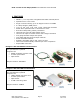
IMC17 / IMCE17 INTEGRATED STEP MOTOR, DRIVER, AND CONTROLLER With Encoder Option USER MANUAL Version 1.
Thank you for purchasing the IMC17 or IMCE17 integrated motor and controller with microstepping driver. This product is warranted to be free of manufacturing defects for one year from the date of purchase. PLEASE READ BEFORE USING Before you begin, ensure there is a suitable DC Power Supply. Do not disconnect the DB-9 cable while power is still being applied to the controller. This will damage the board. Under any circumstances, do not exceed +40 VDC.
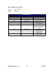
IMC17/IMCE17 User Manual Product: Version: Date: IMC17/IMCE17 1.06 4/3/2009 Version History Version Date Description of Changes 1.00 04/10/2006 New User Manual 1.01 08/07/2006 Updated specs 1.02 08/18/2006 Updated specs 1.03 02/01/2007 1.04 11/02/2007 1.05 12/14/2007 1.
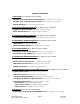
TABLE OF CONTENTS 1. FEATURES Error: Reference source not found Designer’s Kit with RS232 communication Error: Reference source not found Designer’s Kit with USB communication Error: Reference source not found Default Settings Error: Reference source not found 2. ELECTRICAL SPECIFICATIONS Error: Reference source not found Digital I/O Specifications Error: Reference source not found Motor Specifications Error: Reference source not found 3.
Peak current versus Amps/Phase Error: Reference source not found 1. FEATURES • • • • • • • • • • • • • • • NEMA 17, 1.8° step motor integrated with R256 controller/driver Operates from +12V to 40V Single 2 wire bus linking up to 16 stepper motors via RS485 2.
Default Settings Function (command) Running Current (m) Holding Current (h) Step Resolution (j) Top Velocity (V) Acceleration (L) Microstep smoothness (o) Outputs (J) Baud Rate Table 1: Description 30% of 2.0 Amps 10% of max current of 2 Amps 256x 305175 pps (microsteps/sec) L=1000, 6103500 μsteps/sec2 1500 Both are turned off, J0 9600 bps Default Settings 2. ELECTRICAL SPECIFICATIONS Supply Voltage: Peak Current: +12 to +40 VDC 0.1 to 2.
Flow Control None 4. MECHANICAL SPECIFICATIONS Dimensions A. DB-9 connector for I/O, Power and Communication B. Motor Shaft Length: standard length is 0.94”. Customized length is available. C. Motor Shaft Diameter: standard shaft diameter is 0.1968”. Customized diameter length available. D. Overall Body Length: Motor body length is available in various lengths Model IMC17-S (2.69”) Model IMC17-M (2.92”) Model IMC17-L (3.24”) E.
Pin Number Function 1 Ground 2 Index 3 Channel A 4 + 5 VDC 5 Channel B Table 2: Encoder Pinouts 5. PIN ASSIGNMENTS A DB-9 female connector cable receives power and provides the control connections for the IMC17. The DB-9 cable has a 3 pin connector provided for the converter card in order for the controller to communicate with the PC via an RS232 converter card or USB card. Other wires allow the user to solder and program the switch push button and the Opto Sensor, enabling several options.
Figure 1: DB-9 Female Cable Connector (Rear View) Connecting to the RS232 card SP17C pin# 4 SP17C color Black/white 6 Green 3 Brown *USB pin# 1 (RS485A) 2 (GND connect to Power Supply Ground) 3 (RS485B) Table 4 Pin 1 Figure 2 The RS232 card requires power (7-40VDC) Connecting to the USB card SP17C pin# 4 SP17C color Black/white 6 Green 3 Brown *USB pin# 1 (RS485A) 2 (GND connect to Power Supply Ground) 3 (RS485B) Table 5 *Where Pin #1 is located here: Figure 3 The USB converter card does
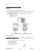
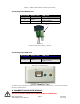
RS232-485 converter card (Figure 4) 1. The RS232 converter card connects to the IMC17 using the DB-9 cable that is provided to you. Opposite the DB-9 cable is a 3-Pin connector which is placed onto the converter card. 2. Your power supply will be connected to the RS232 card where the green header is located. + is for +12-40VDC, - is for the Power Supply Ground. The IMC17 must also be powered via Pin 1 (red wire for Power) and Pin 6 (Green for Ground). 3.
(Figure 5) 1. The USB converter card connects to the IMC17 using the DB-9 cable that is provided to you. The 3-Pin connector is placed onto the converter card. 2. Your power supply will be connected to the IMC17 directly. The USB card is powered via the PC. IMC17’s pin1, Red wire is +12-40VDC, pin 6, Green wire is Ground. 3. Connect the USB card to your PC using the USB cable provided to you. You will need to download driver files (2 of them). You can find them at: http://www.rmsmotion.com 4.
4. Under ‘Connect using’, select the COM connection that corresponds to your PC serial port (i.e. COM 1, COM 2, etc.) then click ‘OK’ 5. Set your Port Settings to default (i.e. 9600 baud, 8 data, no parity, 1 stop bit, no flow control) 6. Turn on local echo by going to: File Properties Settings tab ASCII Setup: Click on the box for “Echo Typed Characters Locally” and click on the box for “Send Line ends with line feeds”. Click “OK”. 7.
In order to set the correct current for your motor, you must program the specified amount in HyperTerminal Current is set based on the Maximum amount of current the controller board can output, which is 2.0 Amps Peak. Below is a table of how much current will be applied to your motor for each setting. Percent 10% 20% 30% 40% 50% 60% 70% 80% 90% 100% = = = = = = = = = = Motor’s Current Rating (Amps) 0.14 0.28 0.42 0.57 0.70 0.85 0.99 1.13 1.27 1.41 Driver’s Equivalent Current (Amps) 0.20 0.40 0.60 0.80 1.
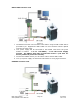
Connecting Multiple IMC17’s If using the RS232-to-RS485 converter card, daisy chain all four wires: power, ground, RS485+ and RS485- prior to plugging into the converter card. Figure 6: Connection using RS232 Converter Card If using the USB485 converter card, connect all the power and ground lines on the units to the main power supply. Then daisy chain the RS485+ and RS485- lines prior to plugging into the USB485 card. Be sure to also ground the USB485 card with Pin 2, ground.
Changing the Address of the Controller Use a screwdriver to turn the dial so the arrow points to the desired Address. Use this number when programming commands. For example, /1P1000R Figure 8: Address Dial Note: New RoHS compliant boards have a Black dial instead of a Red one. Connecting Accessories If you have purchased the Designer’s Kit, there is a Red Push Button and an Optical Sensor included. Follow the schematics below in order to properly assemble accessory pieces.
Any of the four inputs can be connected to a push button.
Optical Sensor Figure 10: Opto Sensor Connection Schematic The Opto Sensor uses Pins 6, 7, and 9. Use the following table to solder the corresponding wires. Optical Sensor DB9 Cable Green Green Black Green Red Yellow White White Table 8 Use the Z command and state the max number of steps you want it to search for home. The unit will either stop at the opto sensor or when it finishes moving your designated number of steps.
Encoder Usage The IMCE17 is not a closed loop system. The encoder does not connect to the controller/driver. A separate PLC or controller system that can talk to the R256 board and understand the E2 encoder can create a closed loop system. The IMCE17 can also be used as reference to home by connecting to an US Digital E2 Encoder.
8. Troubleshooting & FAQ Cannot Type anything in HyperTerminal: Is the correct COM Port selected? Are you using Windows 95? Windows 95 has had problems with its HyperTerminal. Use an operating system of Windows 98 or higher. Are you working on a Laptop? Sometimes there is a shift in Ground on Laptop Serial Ports. Pin 5 on the Serial Port is Ground. Make sure that this is connected to a true ground.
IMC17 will accept commands, but the Motor will stall in the middle of a command: This means there is not enough current being supplied to the Motor. Use the m command to change the current, or run the Motor at a Lower Speed (V command). Or, make the motor accelerate slower using the L command. Halt Command (H01) Issues There are known issues involving the Halt command (i.e., H01) when stored in memory location zero.
Connecting to the old non-RoHS RS232 card SP17C pin# 4 3 6 1 SP17C color Black/white Brown Green Red Table 4 RS232 card pin# A (RS485A) B (RS485B) - (GND) + (PWR) Figure 2 The RS232 card requires power (7-40VDC). Power is then sent to the motor via the Red 4-Pin connector. Figure 5: Connection using RS232 5. The RS232 converter card connects to the IMC17 using the DB-9 cable that is provided to you. The red 4-Pin connector is placed onto the converter card. 6.
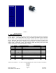
Pin # Pin 1 Pin 2 Pin 3 Pin 4 Old 4-Pin cable Connect New 3-Pin cable to Color/function Color/function Red (PWR) No connection Green (GND) Green (GND) Brown RS485 B (+) Brown RS485 B (+) Black/white RS485 A (-) Black/white RS485 A (-) Pin # -Pin 2 Pin 3 Pin 1 Peak current versus Amps/Phase Where does the 1.4 times come from? Current is continuously changing when a motor steps. If the motor is rated for 1.0 A/Ph, it may receive 0 Amps, 1 Amp, 1.
1.41 AMP (√2) 1 AMP 1 AMP Take a look at position #7. If we were to draw the arrow at position 7 as the hypotenuse of a triangle, it would look like the triangle to our left. Recall from geometry a 90°-45°-45° triangle is a 1-1-√2 combination. The √2, or 1.4 value is also the radius of the dotted circle shown above. Therefore, during certain steps, Phases A or B will receive 1.4 Amps of current. But the average, or RMS current throughout these 8 steps is only 1.0 Amps.