
Manual


S I X P A C K / Q U A D P A C K 7
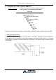
4 C O N N E C T O R A S S I G N M E N T
• Motor Connectors: • Attention: wrong pinning leads to damage to the pcb
• never pull the connectors during operation!
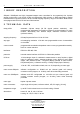
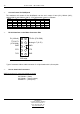
Phase (coil) A of the motor is wired to connectors PHA1 and PHA2, Phase (coil) B to PHB1 and PHB2.
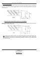
• Electrical Reference Switch
The reference switch is connected to the pins „Ref_In“ and „GND“. Optionally a series resistance of
about 2.2kOhms can be inserted to match EMC demands. In general using an opener, i.e. a normally
closed switch is advisable. So broken cables can be detected. The reference input is equipped with a
Schmitt-trigger.
7PHA2
6PHB1
5PHB2
4GND
3 5V (15mA, 33 OHM)
2
Referenz In (22K Pullup,
TTL)
1 Analog In (0..5V)
8PHA1
PCB edge