
Manual


20 S I X P A C K / Q U A D P A C K
Trinamic Motion Control GmbH & Co KG
Sternstraße 67
D – 20357 Hamburg, Germany
Phone +49-40-51 48 06 - 0
FAX: +49-40-51 48 06 - 60
http://www.trinamic.com
8 I N S T R U C T I O N S E T
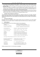
The instruction code is listed in hexadecimal notation, prefixed with $-sign. “motnr“ substitutes the
number of the motor (0=motornr.1 ... 5=motornr.6). Parameters with more than 1 byte are to be
transmitted with the least significant byte (bit 0 – 7) first.
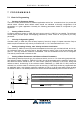
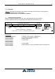
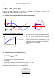
8.1 Adapting the microstep-table to the motor characteristics
alternative motor characteristics (s. CMD $17)
Most motors have varying microstep lengths, due
to this the motor would drive discontinuously for a
sin -/ cos -current. In order to reach a smoother
run, you can drive the motor with an adjusted
current, so that the motor’s characteristics can be
compensated. This current curves are generated
with the 16 values in the table set via CMD $17,
which describe a quarter period.
(s. left)
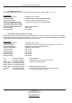
8.2 Calculation of the microstep-frequency
i
div
i
clk
stepmicro
v
clkdiv
f
f
+
−
⋅
+
=
14
2
1
• full step frequency=1/16 microstep frequency
• f
clk
is 20MHz
• clkdiv is the same for all motors (range 0..31)
• v
i
respectively vakt is the velocity of each motor (range: –511..+511)
• div
i
can be parameterized for each motor (range 0..3)
Note: The microstep frequency must not exceed 200kHz.
x
0
2
π
0
π
π
2
4
3
π
)(
ϕ
f
ϕ
box
r
h
o
m
b
circ
le
1
2
π
y
up to 16 micro steps
1 full step
16
m
i
c
ro
s
tep
s
wit
h
in a
q
ua
dra
nt
1
f
u
l
l
step
2
1
2
π
)(
ϕ
f
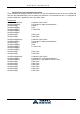
(16 values for gener ati ng the current)
A
0
0
step full / rectangle (1)
triangle(3)
(default) sinus (2)
(3)
(1)
(2)