User's Guide Word Clock Module for the HDSP 9632
Contents 1 2 3 4 5 6 7 8 9 Introduction............................................................ 3 Package Contents .................................................. 3 System Requirements............................................ 3 Power Supply ......................................................... 3 Brief Description and Characteristics................... 3 Technical Specifications and Features................. 4 Hardware Installation .............................................
1. Introduction Thank you for choosing the Hammerfall DSP series. This expansion board adds word clock input and output in professional quality to the HDSP 9632. A transformer-isolated input, a switchable termination and two low jitter outputs extend the powerful capabilities of the HDSP 9632. 2.
6. Technical Specifications and Features • • • • • • • • • • • • • • Low jitter design: < 1 ns in PLL mode, all inputs Internal clock: 800 ps jitter, random spread spectrum Jitter suppression of external clocks: about 30 dB (2.
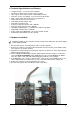
8. First Operation After fitting the WCM (see 7. Hardware Installation) and switching on the computer, activate the push button switch 'Term' located between the BNC jacks. Provided the module is correctly connected to the HDSP 9632, the yellow LED beside the switch must light up. * Technical note: The LED VD108, located on the WCM board, indicates whether the WCM gets the needed 5V from the HDSP or not. This LED is not visible from the outside. 9. Setup and Operation 9.
9.2 House Clock The high quality of the word clock signal offered by the HDSP 9632 allow to use the HDSP 9632 as house clock generator. To simpify this application, the WCM offers two electronically decoupled word clock outputs. 9.3 Extended Modes Due to the HDSP 9632's outstanding clock control a synchronization of the output signal to the input signal is not only possible at identical sample rates, but also at half, quarter, double and quad sample rates.
10. Word Clock 10.1 Technical Background In the analog domain one can connect any device to another device, a synchronization is not necessary. Digital audio is different. It uses a clock, the sample frequency. The signal can only be processed and transmitted when all participating devices share the same clock. If not, the signal will suffer from wrong samples, distortion, crackle sounds and drop outs.
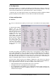
10.2 Cabling and Termination Word clock signals are usually distributed in the form of a network, split with BNC T-adapters and terminated with resistors. We recommend using off-the-shelf BNC cables to connect all devices, as this type of cable is used for most computer networks. You will find all the necessary components (T-adapters, terminators, cables) in most electronics and/or computer stores. The ideal word clock signal should be a 5 Volt square wave having the same frequency as the sample rate.
11. Warranty Each individual Word Clock Module undergoes comprehensive quality control and a complete test in a PC environment at RME before shipping. The usage of high grade components allows us to offer a full two year warranty. We accept a copy of the sales receipt as valid warranty legitimation. RME’s replacement service within this period is handled by the retailer. If you suspect that your card is faulty, please contact your local retailer.
CE This device has been tested and found to comply with the limits of the European Council Directive on the approximation of the laws of the member states relating to electromagnetic compatibility (EMVG) according to EN 55022 class B and EN50082-1. FCC Compliance Statement Certified to comply with the limits for a Class B computing device according to subpart J or part 15 of FCC rules. See instructions if interference to radio reception is suspected.