
User Manual


16
User's Guide Fireface UFX+ © RME
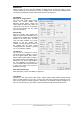
Buffer Size
The setting Buffer Size determines the latency between incoming and outgoing ASIO and WDM
data, as well as affecting system stability (see chapter 9.1).
USB Diagnosis and Errors does not refer to buffer errors, but USB transmission errors. The
display will be reset on any start of a playback/record. More information can be found in chapter
39.3.
Input Options
Word Clock In Termination
Checking this option terminates the word clock input internally with 75 Ohms.
Optical 2 In
Operates as second ADAT input (default). Selecting AES/SPDIF will route the optical input sig-
nal to the AES-Receiver. This mode disables the AES input via XLR.
DSP – EQ+D for Record
Switches EQ and Dynamics of all input channels into the recording path. In case Loopback has
been activated the EQ and Dynamics of the Output channel are within the recording path. See
also chapter 27.6.
MADI Input
Options: Optical - default. Coaxial - the BNC word clock input can be used as coaxial MADI
input. AutoSelect - the UFX+ scans both inputs for a valid MADI signal and activates one as
soon as a MADI signal is found. Split – uses both inputs with 32 channels each.
TMS activates the transmission of Channel Status data and Track Marker information on AES,
SPDIF and MADI inputs. In case these information are not required the feature should be turn-
ed off.
Iso(chronous) Streaming (USB 3 only)
The UFX+ uses a special transmission mode with error correction in record mode. In case the
default mode does not work Isochronous Streaming can be tried. This is the standard’s native
mode for audio transmission and should work with any USB 3 controller. See also chapter 39.3.
Output Options
AES Format
The AES output signal can have the Channel Status Professional or Consumer (SPDIF). This
setting is also valid when ADAT2 has been set as AES/SPDIF output. For further details please
refer to chapter 21.2.
Optical 2 Out
This optical TOSLINK output can operate as ADAT or AES/SPDIF output.
MADI Format
Defines the format of the MADI output signal. MADI can be a 56 or 64 channel signal.
MADI Frame
Sample rates higher than 48 kHz can be transmitted using the normal 48K Frame, or using a
native 96K Frame at the card's output.
MADI Output
Options: Optical - default. Mirror - the BNC word clock output can be used as coaxial MADI
output carrying the same signal as the optical output. Split - uses both outputs with 32 channels
each.