User's Guide Fireface UFX+ The most powerful ThunderboltTM and USB audio interface ever! 24 Bit / 192 kHz 9 ™ SyncAlign ™ TotalMix FX ZLM ™ ™ SyncCheck ™ SteadyClock TM USB 3.
Important Safety Instructions ..................................6 General 1 2 3 4 5 Introduction ...............................................................8 Package Contents .....................................................8 System Requirements ..............................................8 Brief Description and Characteristics.....................8 First Usage - Quick Start 5.1 Connectors – Controls - Display .............................9 5.2 Quick Start .......................................
Installation and Operation - Mac OS X 13 Hardware, Driver and Firmware Installation 13.1 Hardware and Driver Installation ......................... 32 13.2 De-installing the Drivers....................................... 32 13.3 Firmware Update ................................................. 33 14 Configuring the Fireface 14.1 Settings Dialog..................................................... 33 14.2 Clock Modes - Synchronization ........................... 36 15 Mac OS X FAQ 15.1 MIDI doesn't work ...
TotalMix FX 25 Routing and Monitoring 25.1 Overview ..............................................................54 25.2 The User Interface ...............................................56 25.3 The Channels.......................................................57 25.3.1 Settings ........................................................59 25.3.2 Equalizer ......................................................60 25.3.3 Dynamics .....................................................62 25.
Class Compliant Mode 30 31 32 33 34 35 36 General..................................................................... 92 System Requirements ............................................ 92 Operation ................................................................. 93 32.1 Useful Hints.......................................................... 93 32.2 Class Compliant under Windows/Mac OS X ....... 94 Supported Inputs and Outputs.............................. 94 Front panel Operation ........................
Important Safety Instructions ATTENTION! Do not open chassis – risk of electric shock The unit has non-isolated live parts inside. No user serviceable parts inside. Refer service to qualified service personnel. Mains • The device must be earthed – never use it without proper grounding • Do not use defective power cords • Operation of the device is limited to the manual • Use same type of fuse only To reduce the risk of fire or electric shock do not expose this device to rain or moisture.
User's Guide Fireface UFX+ General User's Guide Fireface UFX+ © RME 7
1. Introduction Thank you for choosing the Fireface UFX+. This unique audio system is the premier solution to transfer analog and digital audio data directly to a computer from practically any source. Numerous unique features, well thought-out configuration dialogs, an industry-leading mixing engine and monitoring solution, professional DSP effects and class-leading analog circuits with latest digital converters put the Fireface UFX+ at the very top of the range of computer-based audio interfaces.
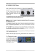
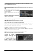
5. First Usage – Quick Start 5.1 Connectors – Controls – Display The front of the Fireface UFX+ features four combined instrument / microphone inputs, two stereo headphone outputs, three rotary encoders with push functionality, a graphical colour display, one MIDI input and output, a USB connector for DURec, and several status LEDs. The Neutrik combo sockets of the four Mic/Line inputs provide XLR and 6.3 mm / 1/4" TRS connection. They have LEDs for Signal (SIG), phantom power (48V) and activated TRS input.
The rear panel of the Fireface UFX+ features eight more analog inputs and outputs, the power socket, and all digital inputs and outputs: Balanced Line Level Inputs. 8 balanced analog inputs via 6.3 mm stereo TRS connectors. Balanced Line Level Outputs. 8 balanced analog outputs, six via 6.3 mm stereo TRS, two via XLR. AES/EBU I/O. XLR. The Fireface UFX+ accepts the commonly used digital audio formats, SPDIF as well as AES/EBU. MADI I/O optical: Standard optical MADI ports (SC). Word Clock I/O. BNC.
5.2 Quick Start After the driver installation (chapter 6 / 13) connect the TRS jacks or the XLR inputs with the analog signal source. The input sensitivity of the rear inputs can be changed in TotalMix (Input Channel Settings, LoGain / +4 dBu and Gain), assuring the highest signal to noise ratio will be achieved. Also try to achieve an optimum input level by adjusting the source itself. Raise the source’s output level until the peak level meters in TotalMix reach about –3 dB.
User's Guide Fireface UFX+ © RME
User's Guide Fireface UFX+ Installation and Operation – Windows User's Guide Fireface UFX+ © RME 13
6. Hardware, Driver and Firmware Installation 6.1 Hardware and Driver Installation To simplify installation it is recommended to first install the drivers before the unit is connected to the computer. But it will also work the other way round. Insert the RME Driver CD into your CD-ROM drive. The driver installer is located in the directory \Thunderbolt for Thunderbolt \MADIface_USB for USB 3 and USB 2.0 (NOT Fireface_USB) Start rmeinstaller.exe and follow the instructions of the installer.
7. Configuring the Fireface 7.1 Settings dialog – Main Tab Configuration of the Fireface UFX+ is done via its own settings dialog. The panel Settings can be opened by clicking on the fire or hammer symbol in the Task Bar's system tray.
Buffer Size The setting Buffer Size determines the latency between incoming and outgoing ASIO and WDM data, as well as affecting system stability (see chapter 9.1). USB Diagnosis and Errors does not refer to buffer errors, but USB transmission errors. The display will be reset on any start of a playback/record. More information can be found in chapter 39.3. Input Options Word Clock In Termination Checking this option terminates the word clock input internally with 75 Ohms.
WDM Devices Allows to freely set which I/Os are available as WDM devices, if these are stereo or multichannel devices (up to 8 channels), and if one or multiple of the currently active WDM devices should have the Speaker property. More details are found in chapter 7.2. Clock Mode Word Clock – Single Speed The word clock output signal usually equals the current sample rate. Selecting Single Speed causes the output signal to always stay within the range of 32 kHz to 48 kHz.
7.2 Option WDM Devices The WDM Devices configuration has one button to enter the edit dialog, a status display showing the number of currently enabled WDM devices, and a listbox to change between Stereo or Multi-Channel devices. The number represents both record and playback devices, so ‘1’ means one input and one output device. The screenshot to the right shows the stereo WDM devices available with the UFX+, and that only Analog 1/2 has been activated. Any number can be activated.
Changing to the tab Speaker presents a list of all currently activated WDM devices. Any of these can now get the Speaker property. Please note that defining more than one device as Speaker usually makes no sense, and the speakers also don’t get numbered or renamed in Windows, so it is impossible to find out which one is which. After leaving the dialog with OK the WDM devices are reloaded so Windows sees their new properties. You can now assign any surround mode, from stereo to 7.
7.3 Tab Global (Thunderbolt only) This tab includes several options that work on all currently installed and supported interfaces. Lock Registry Default: off. Checking this option brings up a dialog to enter a password. Changes in the Settings dialog are no longer written to the registry. As the settings are always loaded from the registry when starting the computer, this method provides an easy way to define an initial state of the Fireface UFX+. Optimize Multi-Client Mixing Default: off.
7.4 Pitch (Thunderbolt only) Usually soundcards and audio interfaces generate their internal clock (master mode) by a quartz. Therefore the internal clock can be set to 44.1 kHz or 48 kHz, but not to a value in between. SteadyClock, RME's sensational Low Jitter Clock System, is based on a Direct Digital Synthesizer (DDS). This superior circuitry can generate nearly any frequency with highest precision.
8. Operation and Usage 8.1 Playback The Fireface UFX+ can play back audio data in supported formats only (sample rate, bit resolution). Otherwise an error message appears (for example at 22 kHz and 8 bit). In the audio application being used, Fireface must be selected as output device. This can often be found in the Options, Preferences or Settings menus under Playback Device, Audio Devices, Audio etc. We recommend switching all system sounds off (via >Control Panel /Sounds<).
8.2 DVD-Playback (AC-3/DTS) AC-3 / DTS When using popular DVD software players like WinDVD and PowerDVD, their audio data stream can be sent to any AC-3/DTS capable receiver using the Fireface's SPDIF output. For this to work, the WDM SPDIF device of the Fireface has to be selected in >Control Panel/ Sound/Playback< as Default device. The DVD software's audio properties now show the options 'SPDIF Out' or similar.
8.3 Channel Count under WDM The Fireface ADAT optical ports allow to record sample rates of up to 192 kHz using a standard ADAT recorder. For this to work single-channel data is spread to two or four ADAT channels using the Sample Multiplexing technique. This reduces the number of available ADAT channels from 8 to 4 or 2 per ADAT port. The same is true for MADI, the number of channels is reduced to 32 or 16 respectively. Whenever the Fireface changes into Double Speed (88.2/96 kHz) or Quad Speed mode (176.
8.5 Analog Recording For recordings via the analog inputs the corresponding record device has to be chosen (Fireface UFX+ Analog (x+x)). The input sensitivity of the rear inputs can be changed in two steps and with adjustable gain in TotalMix (Input Channel Settings, Level), assuring the highest signal to noise ratio will be achieved. A further optimization can be achieved by adjusting the source itself. Raise the source’s output level until the peak level meters in TotalMix reach about –3 dB.
8.7 Clock Modes - Synchronization In the digital world, all devices must be either Master (clock source) or Slave (clock receiver). Whenever several devices are linked within a system, there must always be a single master clock. A digital system can only have one master! If the Fireface’s clock mode is set to 'Master', all other devices must be set to ‘Slave’. The Fireface UFX+ utilizes a very user-friendly, intelligent clock control, called AutoSync.
9. Operation under ASIO 9.1 General Start the ASIO software and select RME Thunderbolt ASIO or ASIO MADIface USB as the audio I/O device or the ASIO audio driver. The Fireface UFX+ supports ASIO Direct Monitoring (ADM). The Fireface UFX+ MIDI I/Os can be used with both MME MIDI and DirectMusic MIDI. 9.2 Channel Count under ASIO At a sample rate of 88.2 or 96 kHz, the ADAT optical input and outputs operate in S/MUX mode, so the number of available channels per port is reduced from 8 to 4.
9.3 Known Problems If a computer does not provide sufficient CPU-power, and/or sufficient USB or PCI bus transfer rates, and/or sufficient PCIe-bus transfer rates, then drop outs, crackling and noise will appear. Raising the buffer size in the Settings dialog of the Fireface UFX+ helps in most cases. It is also recommended to deactivate all PlugIns to verify that these are not the reason for such effects. Further information is found in chapter 39.3.
11. DIGICheck Windows The DIGICheck software is a unique utility developed for testing, measuring and analysing digital audio streams. Although this Windows software is fairly self-explanatory, it still includes a comprehensive online help. DIGICheck 5.82 operates as multi-client ASIO host, therefore can be used in parallel to any software, be it WDM or ASIO, with both inputs and outputs (!). The following is a short summary of the currently available functions: • Level Meter.
12. Hotline – Troubleshooting The newest information can always be found on our website www.rme-audio.com, section FAQ, Latest Additions. The second port ADAT channels don’t seem to work • The optical output ADAT2 has been switched to AES/SPDIF. As can be seen in the block diagram, all channels and their assignments still exist, but the optical transmitter has been disconnected from ADAT2 and is now fed from the AES output (channels 13/14).
User's Guide Fireface UFX+ Installation and Operation – Mac OS X User's Guide Fireface UFX+ © RME 31
13. Hardware, Driver and Firmware Installation 13.1 Hardware and Driver Installation After the Fireface has been connected to the computer and switched on install the drivers from the RME Driver CD. The driver files are located in the folder \MADIface_USB and \Thunderbolt. Installation works automatically by a double-click on the file Fireface USB.pkg or RME Thunderbolt.pkg. RME recommends downloading the latest driver version from the RME website.
13.3 Firmware Update The Flash Update Tool updates the firmware of the Fireface UFX+ to the latest version. It requires an already installed Thunderbolt or USB driver. Start the program RME UFX+ Flash Update Tool. The Flash Update Tool displays the current revision of the UFX+ firmware, and whether it needs an update or not. If so, simply press the 'Update' button. A progress bar will indicate when the flash process is finished (Verify Ok). After the update the Fireface UFX+ needs to be reset.
Input Options Word Clock - Termination Checking this option terminates the word clock input internally with 75 Ohms. Optical 2 In SPDIF will turn the optical input into an optical SPDIF input, ADAT into an ADAT input (default). Please note that using the optical input with SPDIF disables the AES input via XLR. MADI Input Options: Optical - default. Coaxial - the BNC word clock input can be used as coaxial MADI input.
Sample Rate Used to set the current sample rate. This is the same setting as in the Audio MIDI Setup, just added here for your convenience. Clock Source The unit can be configured to use its own clock (Internal = Master), or one of the input signals (Word, AES, ADAT1, ADAT2, MADI optical, MADI coaxial). If the selected source isn't available (Input Status No Lock), the unit will change to the next available one (AutoSync). If none is available then the internal clock is used.
14.2 Clock Modes - Synchronization In the digital world, all devices must be either Master (clock source) or Slave (clock receiver). Whenever several devices are linked in a system, there must always be a single master clock. A digital system can only have one master! If the Fireface’s clock mode is set to 'Master', all other devices must be set to ‘Slave’. The Fireface UFX+ utilizes a very user-friendly, intelligent clock control, called AutoSync.
15. Mac OS X FAQ 15.1 MIDI doesn't work In some cases the applications do not show the MIDI port. The reason for this is usually visible within the Audio MIDI Setup. It displays no RME MIDI device, or the device is greyed out and therefore inactive. Mostly, removing the greyed out device and searching for MIDI devices again will solve the problem. The Fireface’ MIDI is class compliant. Therefore it comes without a driver.
15.5 Various Information The driver of the Fireface requires at least Mac OS 10.6. Programs that don't support card or channel selection will use the device chosen as Input and Output in the System Preferences – Sound panel. Via Launchpad – Other – Audio MIDI Setup the Fireface can be configured for the system wide usage in more detail. Programs that don't support channel selection will always use channels 1/2, the first stereo pair.
17. DIGICheck Mac The DIGICheck software is a unique utility developed for testing, measuring and analysing digital audio streams. Although the software is fairly self-explanatory, it still includes a comprehensive online help. DIGICheck 0.70 operates in parallel to any software, showing all input data. The following is a short summary of the currently available functions: • Level Meter. High precision 24-bit resolution, 2/8/94 channels.
18. Hotline – Troubleshooting The newest information can always be found on our website www.rme-audio.com, section FAQ, latest Additions. The unit and drivers have been installed correctly, but playback does not work: • Is Fireface UFX+ listed in the System Profiler? (Vendor ID 2613). • Has Fireface been selected as current playback device in the audio application? The 8 ADAT channels don’t seem to work • The optical output ADAT2 has been switched to AES/SPDIF.
User's Guide Fireface UFX+ Inputs and Outputs User's Guide Fireface UFX+ © RME 41
19. Analog Inputs 19.1 Line Rear The Fireface has eight balanced Line inputs as 1/4" TRS jacks on the back of the unit. The electronic input stage is built in a servo balanced design which handles unbalanced (mono jacks) and balanced (stereo jacks) correctly, automatically adjusting the level reference. When using unbalanced cables with TRS jacks: be sure to connect the 'ring' contact of the TRS jack to ground. Otherwise noise may occur, caused by the unconnected negative input of the balanced input.
20. Analog Outputs 20.1 Line The short circuit protected, low impedance line outputs of channels 3 to 8 are available as 1/4" TRS jacks on the back of the unit. The electronic output stage is built in a servo balanced design which handles unbalanced (mono jacks) and balanced (stereo jacks) correctly.
In case the Phones outputs should operate as line outputs, an adapter TRS plug to RCA phono plugs, or TRS plug to TS plugs is required. The pin assignment follows international standards. The left channel is connected to the tip, the right channel to the ring of the TRS jack/plug. 21. Digital Connections 21.1 ADAT The ADAT optical inputs of the Fireface UFX+ are fully compatible with all ADAT optical outputs.
Input Thanks to a highly sensitive input stage SPDIF coaxial can be fed too by using a simple cable adapter phono/XLR. To achieve this, pins 2 and 3 of a male XLR plug are connected individually to the two pins of a phono plug. The cable shielding is only connected to pin 1 of the XLR - not to the phono plug. In AES operation, identical signals are available at both the optical and the XLR output. An obvious use for this would be to connect two devices, i.e.
21.4 MIDI Fireface UFX+ offers two MIDI I/O via four 5-pin DIN sockets. The MIDI ports are added to the system by the driver. Using MIDI capable software, these ports can be accessed under the name UFX+ MIDI Port. All RME MADI devices support the invisible transmission of MIDI via MADI. MIDI data can be transmitted from/to other RME devices with MADI ports, without any additional line or cabling between computer (MADI interface) and external units.
The received word clock signal can be distributed to other devices by using the word clock output. With this the usual T-adapter can be avoided, and the Fireface UFX+ operates as Signal Refresher. This kind of operation is highly recommended, because • • • input and output are phase-locked and in phase (0°) to each other SteadyClock removes nearly all jitter from the input signal the exceptional input (1 Vpp sensitivity instead of the usual 2.
22.3 Cabling and Termination Word clock signals are usually distributed in the form of a network, split with BNC T-adapters and terminated with resistors. We recommend using off-the-shelf BNC cables to connect all devices, as this type of cable is used for most computer networks. You will find all the necessary components (T-adapters, terminators, cables) in most electronics and/or computer stores. The latter usually carries 50 Ohms components.
User's Guide Fireface UFX+ Stand-Alone Operation User's Guide Fireface UFX+ © RME 49
23. Operation and Usage 23.1 General Using the three rotary encoders and the clear colour display the Fireface UFX+ can be configured and set up completely at the device. Additionally internal memory allows for the permanent storage of six different states of the unit. Therefore the Fireface UFX+ is able to operate fully stand-alone, without any connected computer. In stand-alone operation it can transform into totally different devices by the simple click of a button.
24. Examples 24.1 12-Channel AD/DA-Converter TotalMix' super-flexible routing functions make it easy to turn the UFX into a 12-channel AD/DA converter. It’s easy to build the setup. For a clean start perform a Total Reset from the Options menu. Then select the ADAT Output 1/2 in the third row, and pull up the faders of the Analog input 1/2 in the first row. Then select ADAT 3/4, pull up Analog 3/4 and so on until all 12 analog inputs are routed to the corresponding 12 (8+4) ADAT channels.
User's Guide Fireface UFX+ © RME
User's Guide Fireface UFX+ TotalMix FX User's Guide Fireface UFX+ © RME 53
25. Routing and Monitoring 25.1 Overview The Fireface UFX+ includes a powerful digital real-time mixer, the Fireface UFX+ mixer, based on RME’s unique, sample-rate independent TotalMix technology. It allows for practically unlimited mixing and routing operations, with all inputs and playback channels simultaneously, to any hardware outputs. TotalMix FX adds 3-band parametric Equalizer, Low Cut, Echo, Reverb, Compressor, Expander and Auto Level.
User's Guide Fireface UFX+ © RME 55
25.2 The User Interface The visual design of the TotalMix mixer is a result of its capability to route hardware inputs and software playback channels to any hardware output. The Fireface UFX+ has 94 input channels, 94 software playback channels, and 94 hardware output channels: TotalMix can be used in the above view (View Options 2 Rows).
25.3 The Channels A single channel can be switched between mono and stereo mode. The mode is set in the channel settings. Channel name. The name field is the preferred place to select a channel by a mouse click. A double click opens a dialog to assign a different name. The original name will be shown when activating the option Names in the View Options. Panorama. Routes the input signal freely to the left and right routing destination (lower label, see below).
The lowest field shows the current routing target. A mouse click opens the routing window to select a routing target. The list shows all activated routings of the current channel by arrows in front of the listed entries, the current one is shown in bold letters. An arrow is only shown with an activated routing. A routing is seen as activated when audio data is sent. As long as the fader is set to −∞ the current routing will be shown in bold letters, but not have an arrow in the front. Trim Gain.
25.3.1 Settings A click on the tool symbol opens the channel’s Settings panel with differing elements. For example the option Inst exists only in input channels 9-12, and the ADAT channels do not offer the phantom power option. Stereo. Switches the channel to mono or stereo mode. 48V. Activates phantom power at the corresponding input. Serves as power supply for high quality condenser mics. This option should stay off with other sources to prevent failure by spikes. Inst.
Besides Stereo/Mono, Phase L und Phase R the settings of the Hardware Outputs have further options: Level. Sets the reference levels of the 8 analog Line outputs. The available settings are -10 dBV, +4 dBu and HiGain. The outputs 1/2 additionally offer +24 dBu. The Phones (channels 9-12) have a Low and High setting to choose from. FX Return. The effect signal (Echo and Reverb) is mixed to the respective hardware output by the duo knob/small fader. Talkback.
The frequency graphics give a precise overview of the filter results. Overlapping filters influence each other. This can be used to achieve more than 20 dB amplitude, or to generate difficult frequency response optimizations. Note: TotalMix has an internal headroom of 24 dB. Extreme boosts with overlapping filters can therefore cause an internal overload. In any case such an overload is displayed by the Over LED of the channel’s level meter. Preset.
25.3.3 Dynamics A click on D opens the Dynamics panel with Compressor, Expander and Auto Level. They are available in all input and output channels, and affects all routings of the respective channel. Dynamics. Activated by this button. Thresh. Threshold where Compressor or Expander start to work. The Compressor is adjustable from -60 dB to 0 dB, the Expander is adjustable from -99 dB to -20 dB. Ratio. Ratio of input to output signal. Defines the intensity of the signal processing. Adjustable from 1 to 10.
25.4 Section Control Room In the section Control Room the menu Assign defines the Main Out which is used for listening in the studio. For this output the functions Dim, Recall, Mono, Talkback, External In and Mute FX are automatically applied. At the unit the VOLUME knob follows this assignment. Additionally the channel will be shifted from the Hardware Outputs into the Control Room section, and renamed Main. The same happens when assigning Main Out B or the Phones.
25.5 The Control Strip The Control Strip on the right side is a fixed element. It combines different functions that are either required globally, or constantly used, and therefore should not be hidden in a menu. It can still be hidden via the top menu Window – Hide Control Strip. The areas described in the following chapters can be minimized by a click on the arrow in their title bar. Device selection. Select the unit to be controlled in case more than one is installed on the computer. FX - DSP Meter.
25.5.1 View Options The field Show combines different functions of routing, the level meters and the mixer view. Routing Mode ¾ Submix. The Submix view (default) is the preferred view and delivers the quickest overview, operation and understanding of TotalMix. The click on one of the Hardware Output channels selects the respective submix, all other outputs are darkened. At the same time all routing fields are set to this channel.
25.5.2 Snapshots - Groups Snapshots. Snapshots include all mixer settings, but no graphical elements like window positions, window size, number of windows, visible EQs or Settings, scroll states, Presets etc. Only the state wide/narrow of the channels is registered. Moreover the Snapshot is only temporarily stored. Loading a Workspace causes the loss of all stored Snapshots, when these all had not been saved before in a Workspace, or separately via File / Save Snapshot as.
Hidden channels in Mixer/Matrix are still fully functional. An existing routing/mixing/FX processing stays active. But as the channel is no longer visible it can not be edited anymore. At the same time the hidden channels are removed from the list of remote controllable channels, to prevent them from being edited unnoticed. Hidden channels in MIDI Remote x are removed from the list of remote controllable channels. Within an 8-channel block of a Mackie compatible control they are skipped.
25.5.4 Scroll Location Markers Another feature to improve overview and working with TotalMix FX are scroll location markers (TotalMix view only). These are displayed automatically when the horizontal size of the TotalMix FX window is smaller than the channel display requires. Shown on the right side of the scrollbar of each row they have four elements: ¾ ¾ ¾ ¾ Arrow to the left. A left mouse click let the channels scroll to the very first one, or most left. 1. Marker number 1.
25.6 Reverb and Echo A click on FX in the View Options / Show brings up the Output FX panel. Here all parameters for the effects Reverb and Echo are adjusted. Reverb. Activated by the On button. Type. Lists different reverb types for selection. Available are: ¾ Rooms Small, Medium, Large, Walls. Room simulation of rooms in different size and behaviour. ¾ Shorty provides a short, rich and warm reverb. ¾ Attack slaps back. ¾ Swagger enriches and blows up the original sound source.
General Settings PreDelay. Delay of the reverb signal. Adjustable from 0 ms up to 999 ms. Low Cut. High-pass filter before the reverb generation, removes low frequency signals which should not cause a reverb sound. Adjustable from 20 Hz up to 500 Hz. High Cut. Low-pass filter after the reverb generation. A reduction of the treble often lets the reverb sound more natural. Adjustable from 5 kHz up to 20 kHz. Smooth. Softens the reverb effect, affects stereo width, density and sound colour.
Echo. Activated by the On button. Type. Lists different echo algorithms for selection. Available are: ¾ Stereo Echo. Separated echo generators on left and right channel. As a result the echo follows the sound source within the stereo field. ¾ Stereo Cross. Echo generator on left and right channel with cross coupled feedback which is only working for the stereo parts of the input signal. In case the input signal is only left or right the Stereo Cross acts exactly like the Pong Echo. ¾ Pong Echo.
25.7 Preferences The dialog Preferences can be opened via the Options menu or directly via F2. Level Meters ¾ Full scale samples for OVR. Number of consecutive samples to trigger an over detection (1 to 10). ¾ Peak Hold Time. Hold time of the peak value. Adjustable from 0.1 up to 9.9 s. ¾ RMS +3 dB. Shifts the RMS value by +3 dB, so that full scale level is identical for Peak and RMS at 0 dBFS. Mixer Views ¾ FX Send follows highest Submix. Locks the FX Send knob to the channel fader.
Snapshots ¾ Do not load Main volume/balance. The values stored in the Snapshot are not loaded for the Main Out, so the current setting is not changed. Device Handling ¾ Always init DSP devices with TotalMix FX settings. Used to suppress the mismatch message after using the unit stand-alone. Settings in the unit are lost. ¾ Count MADI Channels per port. Not available with the Fireface UFX+. ¾ Disable ASIO Direct Monitoring. Disables ASIO Direct Monitoring (ADM) for the Fireface UFX+ within TotalMix FX.
25.8 Settings The dialog Settings can be opened via the Options menu or directly via F3. 25.8.1 Mixer Page On the mixer page some typical settings for the mixer operation are set, like Talkback source, Dim amount when Talkback is active, the stored main volume or the input used for the External Input function. Talkback ¾ Input. Selects the input channel of the Talkback signal (microphone in control room). Default: None. ¾ Dim. Amount of attenuation of the signals routed to the Phones in dB.
25.8.2 MIDI Page The MIDI page has four independent settings for up to four MIDI remote controls, using CC commands or the Mackie Control protocol. Index Select one of four settings pages and thus remote controls. Settings are remembered automatically. To activate or deactivate any of the four remote controls check or uncheck ‘In Use’. MIDI Remote Control ¾ MIDI In. Input where TotalMix receives MIDI Remote data. ¾ MIDI Out. Output where TotalMix sends MIDI Remote data. ¾ Disable MIDI in background.
25.8.3 OSC Page The OSC page has four independent settings for up to four MIDI remote controls via Open Sound Control (OSC). This is a network based remote protocol that can be used for example by Apple’s iPad with the app TouchOSC or Lemur to wirelessly remote control TotalMix FX running on a Mac or Windows computer. Index Select one of four settings pages and thus remote controls. Settings are remembered automatically. To activate or deactivate any of the four remote controls check or uncheck ‘In Use’.
25.8.4 Aux Devices The RME OctaMic XTC is a highly flexible hi-quality 8-channel microphone, line and instrument preamp with integrated ADconversion to ADAT, AES/EBU and MADI, plus 4 channels of DA-conversion for monitoring. It can be used as universal front-end for the Fireface UFX+ and other interfaces. To simplify operation the most important parameters of the XTC (gain, 48V, phase, mute, AutoSet) can be controlled directly from the TotalMix FX input channels.
25.9 Hotkeys and Usage TotalMix FX has many hotkeys and mouse/hotkey combinations to speed up and simplify the usage. The below description refers to Windows. On Mac substitute Ctrl in the below list with the command key (u). The Shift key enables a fine-tuning of the gain with all faders and in the Matrix. On all knobs it will speed up the setting. A click on a fader with held down Shift key adds the fader to the temporary fader group.
25.10 Menu Options Deactivate Screensaver: When active (checked) any activated Windows screensaver will be disabled temporarily. Always on Top: When active (checked) the TotalMix window will always be on top of the Windows desktop. Note: This function may result in problems with windows containing help text, as the TotalMix window will even be on top of those windows, so the help text isn't readable. Enable MIDI /OSC Control: Activates external MIDI control of the TotalMix mixer.
Operational Mode. Defines TotalMix FX basic operational mode. Choices are Full Mode (default, mixer active, all routing options available), and Digital Audio Workstation Mode (straight playback routing, no input mix). See chapter 29 for details. Store Current state into device. The unit can store up to 6 setups (the current state) in its own memory. This function is especially useful when working in stand-alone mode. 25.11 Menu Window Zoom Options 100%, 135%, 200%.
26.3 Operation Using the Matrix is a breeze. It is very easy to indentify the current crosspoint, because the outer labels light up in orange according to the mouse position. ¾ If input 1 is to be routed to output 1, use the mouse and click one time on crosspoint In 1 / AN 1 with held down Ctrl key. Two green 0.0 dB field pop in, another click removes them.
27.4 Delete a Submix The easiest and quickest way to delete complex routings is by selection of the according output channel in the mixer view by a right mouse click, and selection of the menu entry Clear Submix. As TotalMix FX includes an unlimited undo the delete process can be undone without any problem. 27.5 Copy and Paste everywhere The above three tips use functions found in the right click context menu available on all channels of the mixer view.
The block diagram also shows why with activated Loopback the EQ of the Hardware Output is now within the record path. With Loopback active the EQ of the input is not in the record path, only in the monitoring path, even when the Option DSP – EQ+D for Record is activated.
27.7 MS Processing The mid/side principle is a special positioning technique for microphones, which results in a mid signal on one channel and a side signal on the other channel. This information can be transformed back into a stereo signal quite easily. The process sends the monaural mid channel to left and right, the side channel too, but phase inverted (180°) to the right channel. For a better understanding: the mid channel represents the function L+R, while the side channel represents L-R.
28. MIDI Remote Control 28.1 Overview TotalMix can be remote controlled via MIDI. It is compatible to the widely spread Mackie Control protocol, so TotalMix can be controlled with all hardware controllers supporting this standard. Examples are the Mackie Control, Tascam US-2400 or Behringer BCF 2000. Additionally, the stereo output faders (lowest row) which are set up as Main Out in the Control Room section can also be controlled by the standard Control Change Volume via MIDI channel 1.
28.3 Setup Open the Preferences dialog (menu Options or F3). Select the MIDI Input and MIDI Output port where your controller is connected to. When no feedback is needed select NONE as MIDI Output. Check Enable MIDI Control in the Options menu. 28.4 Operation The channels being under Mackie MIDI control are indicated by a colour change of the name field, black turns to brown. The 8-fader block can be moved horizontally and vertically, in steps of one or eight channels. Faders can be selected to gang them.
28.5 MIDI Control The hardware output which is set up as Main Out can be controlled by the standard Control Change Volume via MIDI channel 1. With this, the main volume of the Fireface is controllable from nearly any MIDI equipped hardware device. Even if you don't want to control all faders and pans, some buttons are highly desired to be available in 'hardware'. These are mainly the Talkback and the Dim button, and the monitoring options (listen to Phones submixes).
Examples for sending MIDI strings: - Set input 1 to 0 dB: B0 66 68 - Set input 17 to maximum attenuation: B1 66 0 - Set playback 1 to maximum: B4 66 7F - Set Output 16 to 0 dB: B8 75 68 Note: Sending MIDI strings requires to use programmer's logic for the MIDI channel, starting with 0 for channel 1 and ending with 15 for channel 16.
In stand-alone mode the unit always operates in View Submix mode. Only this way the routing destination can be changed, and several mixdowns/submixes can be set up quickly and easily. If the current TotalMix setup is transferred into the Fireface via 'Flash current mixer state', the currently selected submix output is also pre-configured in the hardware for stand-alone MIDI remote operation.
28.7 Loopback Detection The Mackie Control protocol requires feedback of the received commands, back to the hardware controller. So usually TotalMix will be set up with both a MIDI input and MIDI output. Unfortunately any small error in wiring and setup will cause a MIDI feedback loop here, which then completely blocks the computer (the CPU). To prevent the computer from freezing, TotalMix sends a special MIDI note every 0.5 seconds to its MIDI output.
User’s Guide Fireface UFX+ Class Compliant Mode User's Guide Fireface UFX+ © RME 91
30. General The Fireface UFX+ operates in three different modes: driver-based USB2/3 and Thunderbolt, stand-alone mode, and Class Compliant mode. The latter describes a standard that is natively supported by operating systems like Windows, Mac OS X and Linux. No proprietary drivers are required, the device will be directly recognized when the CC firmware is loaded. The natively available features will be limited in comparison to those provided by the RME driver for the UFX+.
32. Operation In factory default setting Interface Mode – Auto the UFX+ will not automatically switch to CC mode as soon as an iPad or iPhone is connected. Instead it switches to mode USB 2, and iPhone/iPad show a warning of an unsupported device. The CC mode always has to be activated manually. Activation of the Class Compliant mode: Remove USB and Thunderbolt cable from the UFX+. Press SETUP/REV. Turn encoder 1 until Options appears in the display. Turn encoder 2 until Hardware/Diagnosis appears.
32.2 Class Compliant Mode under Windows and Mac OS X Windows does not support USB Audio 2.0 directly. The UFX+ will be detected, but automatic driver installation will fail. This is important to remember. Connecting the UFX+ to the PC after having it used with the iPhone/iPad one might forget that it is still in CC mode. You might loose a lot time trying to repair your driver installation – when all you need to do is set the unit back to normal mode. Mac OS X supports USB Audio 2.
While the MIDI I/Os will send and receive Sysex messages, not all apps are ready to do this. The app Midi Tool Box can be used to verify that the UFX+ is working correctly, and the problem lies somewhere else. 34. Front panel operation The front panel operation is identical to the one under Windows and OS X, or standalone operation.
36. Setups TotalMix FX can transfer all current settings to the device (Options/Store Current State into Device). There are six memory slots (Setups) available. An example: ¾ Inputs with no processing, gain set to +30 dB and phantom power active. Outputs without processing, faders for 1/2 set to 0 dB, 9/10 at – 20 dB, clock mode master, saved in Setup 1.
User’s Guide Fireface UFX+ DURec™ - Direct USB Recording User's Guide Fireface UFX+ © RME 97
37. Direct USB Recording 37.1 Overview The Fireface UFX+ can record and playback up to 76 channels of audio via the USB port on the front panel. This functionality is provided by the internal DSP and is therefore independent from a Windows or Mac computer connected via USB or Thunderbolt. As all settings are also available directly at the unit it is possible to even record a whole live concert completely without a computer.
Record View. Switches from Mixer View to Record View. In Record View Mute and Solo buttons in first and third row are replaced by Play and Record (Arm) buttons. A click on the Playback button opens a dialog to assign channels. A flashing playback button indicates playback channels have been selected that are not found in the played back file. A playback is not only possible at the outputs but also at the mixer input.
Record. Remain (Rec.). The medium’s remaining total record time (limited by disk space and a maximum of 100 files). Free. Free space on the media. Max R/W Time. The time needed for the read or write operation. Details see chapter 37.5. Playback. Remain (File). Remaining play time of the current file. Next. Shows and allows to select the next file to be played. Play Mode.
37.3 Limitations and Important Notes The media must be formatted as FAT32, primary type. Logical partitions are not supported. With volumes having more than one partition, a different partition than default partition 1 can be selected in Rec/Play Settings, USB Media. A recording is always stopped when the sample rate changes. Changing the record configuration (armed channels) is not possible during an ongoing recording.
The block diagram shows the signal flow for various situations, depending on the state of Loopback, EQ for Record and Play active. In the diagram Loopback and EQ are switched to off, but a playback is active in the input. Some extra notes that are worth to be pointed out again: • The signal recorded by audio software is usually that from the input.
The free software is available for Windows and Mac OS X and can be downloaded from the RME website, www.rme-audio.com, section Downloads / Software. Since firmware DSP 39 the UFX+ adds some meta data to the recorded files, like date, time, recording device and channel number. The WAV File Batch Processor reads these data and writes them accordingly into the generated wav files. Additionally the processor adds the channel info to the file names. For example UFX01_I_05.
User's Guide Fireface UFX+ © RME
User's Guide Fireface UFX+ Technical Reference User's Guide Fireface UFX+ © RME 105
38. Technical Specifications 38.1 Analog AD, Line In 1-8, rear • Resolution AD: 24 bit • Signal to Noise ratio (SNR): 113 dB RMS unweighted, 116 dBA • Frequency response @ 44.1 kHz, -0.1 dB: 5 Hz – 20.8 kHz • Frequency response @ 96 kHz, -0.5 dB: 3 Hz – 45.8 kHz • Frequency response @ 192 kHz, -1 dB: 2 Hz – 92 kHz • THD: < -110 dB, < 0.00032 % • THD+N: < -104 dB, < 0.00063 % • Channel separation: > 110 dB • Maximum input level: +19 dBu • Input: 6.
DA, Line Out 3-8, rear • Resolution: 24 bit • Dynamic range (DR): 115 dB RMS unweighted, 118 dBA • Frequency response @ 44.1 kHz, -0.5 dB: 5 Hz – 20.8 kHz • Frequency response @ 96 kHz, -0.5 dB: 5 Hz – 45 kHz • Frequency response @ 192 kHz, -1 dB: 5 Hz - 89 kHz • THD: < -110 dB, < 0.00032 % • THD+N: < -104 dB, < 0.00063 % • Channel separation: > 110 dB • Maximum output level: +19 dBu • Output: 6.
38.4 Digital Inputs MADI • Optical via FDDI duplex SC connector • 62.5/125 and 50/125 compatible • Coaxial via BNC (Word Clock input), 75 Ohm • High-sensitivity input stage (< 0.
38.5 Digital Outputs MADI • Optical via FDDI duplex SC connector • 62.
39. Technical Background 39.1 Lock and SyncCheck Digital signals consist of a carrier and the data. If a digital signal is applied to an input, the receiver has to synchronize to the carrier clock in order to read the data correctly. To achieve this, the receiver uses a PLL (Phase Locked Loop). As soon as the receiver meets the exact frequency of the incoming signal, it is locked. This Lock state remains even with small changes of the frequency, because the PLL tracks the receiver's frequency.
39.2 Latency and Monitoring The term Zero Latency Monitoring has been introduced by RME in 1998 for the DIGI96 series of audio cards. It stands for the ability to pass-through the computer's input signal at the interface directly to the output. Since then, the idea behind has become one of the most important features of modern hard disk recording.
AD/DA Offset under ASIO and OS X: ASIO (Windows) and Core Audio (Mac OS X) allow for the signalling of an offset value to correct buffer independent delays, like AD- and DA-conversion or the Safety Buffer described below. An analog loopback test will then show no offset, because the application shifts the recorded data accordingly. Because in real world operation analog record and playback is unavoidable, the drivers include an offset value matching the Fireface's converter delays.
Current Fireface UFX+ USB 3 Compatibility Information ¾ ¾ Fully compatible to Intel's USB 3 implementation which - on current Windows and Mac computers - is part of the chipset. USB 3 sockets that are connected via an internal cable (not directly soldered onto the motherboard) can cause transmission errors (these are shown in the Settings dialog). Fully compatible to AMD's USB 3 implementation.
Especially with notebooks it can happen that all internal devices and all the sockets/ports are connected to the same controller, with the second controller not used at all. In that case all devices have to use the same bus and will interfere with each other. A computer blocked for a short time – no matter if ASIO or WDM – will lose one or more data packets. Such problems can only be solved by increasing the buffer size (latency). 39.
39.5 DS - Double Speed Sample rates above 48 kHz were not always taken for granted, and are still not widely used because of the CD format (44.1 kHz) dominating everything. Before 1998 there were no receiver/transmitter circuits available that could receive or transmit more than 48 kHz. Therefore a work-around was used: instead of two channels, one AES line only carries one channel, whose odd and even samples are being distributed to the former left and right channels.
39.7 Noise level in DS / QS Mode The outstanding signal to noise ratio of the Fireface UFX+ AD-converters can be verified even without expensive test equipment, by using record level meters of various software. But when activating the DS and QS mode, the displayed noise level will rise from -113 dB to -105 dB at 96 kHz, and –79 dB at 192 kHz. This is not a failure. The software measures the noise of the whole frequency range, at 96 kHz from 0 Hz to 48 kHz (RMS unweighted), at 192 kHz from 0 Hz to 96 kHz.
39.9 MADI Basics MADI, the serial Multichannel Audio Digital Interface, has been defined already in 1989 as an extension of the existing AES3 standard following several manufacturers' wish. The format also known as AES/EBU, a balanced bi-phase signal, is limited to two channels. Simply put, MADI contains 28 of those AES/EBU signals in serial, i. e. after one another, and the sample rate can still even vary by +/-12.5%. The limit which cannot be exceeded is a data rate of 100Mbit/s.
40. Diagrams 40.
40.2 Connector Pinouts TRS jacks of analog input / output The stereo 1/4" TRS jacks of the rear analog inputs and outputs are wired according to international standards: Tip = + (hot) Ring = – (cold) Sleeve = GND The servo balanced input and output circuitry allows to use monaural TS jacks (unbalanced) with no loss in level. This is the same as when using a TRS-jack with ring connected to ground.
User's Guide Fireface UFX+ © RME
User's Guide Fireface UFX+ Miscellaneous User's Guide Fireface UFX+ © RME 121
41. Accessories RME offers several optional components for the Fireface UFX+: Part Number Description OK0100PRO OK0200PRO OK0300PRO OK0500PRO OK1000PRO Optical cable, TOSLINK, 1 m (3.3 ft) Optical cable, TOSLINK, 2 m (6.6 ft) Optical cable, TOSLINK, 3 m (9.9 ft) Optical cable, TOSLINK, 5 m (16.4 ft) Optical cable, TOSLINK, 10 m (33 ft) MADI0.5S MADI1S MADI3D MADI6D MADI10D MADI20D MADI50D MADI Optical Cable, Simplex, 0.5 m (1.6 ft) MADI Optical Cable, Simplex, 1 m (3.
43. Appendix RME news, driver updates and further product information are available on our website: http://www.rme-audio.com Distributor: Audio AG, Am Pfanderling 60, D-85778 Haimhausen, Tel.: (49) 08133 / 918170 Manufacturer: IMM electronics GmbH, Leipziger Strasse 32, D-09648 Mittweida Trademarks All trademarks, registered or otherwise, are the property of their respective owners. RME, DIGICheck and Hammerfall are registered trademarks of RME Intelligent Audio Solutions.
44. CE / FCC Compliance CE This device has been tested and found to comply with the limits of the European Council Directive on the approximation of the laws of the member states relating to electromagnetic compatibility according to RL2004/108/EG, and European Low Voltage Directive RL2006/95/EG. FCC This device complies with Part 15 of the FCC Rules.