
User Manual


User's Guide Digiface USB © RME
7
5. First Usage – Quick Start
5.1 Connectors – LEDs
The front of the Digiface USB features the USB connector, five status LEDs and the head-
phone output.
The USB power LED indicates sufficient power supply (USB bus power).
Sync LEDs 1 to 4 show the current status of all optical inputs. With no input signal they stay
dark. With recognized but not synchronous ADAT or SPDIF signal they flash. With a valid and
synchronous input signal they stay constantly lit.
USB 2.0: Standard USB socket for connection to the computer. Please make sure the Digiface
USB can have the full voltage/current delivered from the computer by using hi-quality USB ca-
bles (like the one included), no USB extension cables and no USB hubs. When connected to
USB 3 only the USB 2 protocol will be used.
Phones is a low impedance line
output of highest quality. It provides a
sufficient and undistorted volume
even when used with headphones.
In case this output should operate as
Line output, an adapter TRS plug to
RCA phono plugs, or TRS plug to TS
plugs is required.
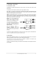
The pin assignment follows in-
ternational standards. The left
channel is connected to the tip, the
right channel to the ring of the TRS
jack/plug.
The rear of the Digiface USB features 4 optical inputs and 4 optical outputs in TOSLINK format.
These are compatible with ADAT optical and SPDIF optical.
5.2 Quick Start
After the driver installation (chapter 6 / 13), connect the inputs and outputs with the respective
signal source (AD/DA converter, ADAT recorder, digital mixing desks etc).
Level adjustment of the analog output Phones is available in TotalMix FX. The output is opti-
mized for phones, but can also be used as line output
TotalMix FX remembers all settings, and loads these automatically when the Digiface USB driv-
ers are loaded.