
User Manual

User's Guide Digiface USB © RME
13
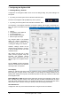
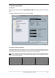
Limit ASIO to 32 Channels
Some software crashes when presented with more than 32 ASIO channels. This workaround
removes the phones output, which can still be accessed and used via TotalMix FX.
Buffer Size
The setting Buffer Size determines the latency between incoming and outgoing ASIO and WDM
data, as well as affecting system stability (see chapter 7.1 / 9).
USB Diagnosis shows specific USB transmission errors (CRC5, usually 0) and general errors.
If the unit detects a record or playback error the number shown will no longer be 0. An audio
reset is performed automatically. The counter is reset on start of playback/record. More informa-
tion can be found in chapter 26.2.
Output Format
Defines the format of the optical output signals. Choices are ADAT and SPDIF.
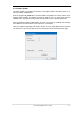
Options
Output
Removing the crosscheck at TotalMix deactivates TotalMix completely, and activates a 1:1 rout-
ing. All input and output data is going straight to record/coming from playback, with no mixing or
routing involved.
Input
TMS activates the transmission of Channel Status data and Track Marker information from the
SPDIF input signal. DIGICheck allows to read out those information. This feature is not avail-
able for input 1.
WDM Devices
Allows to freely set which I/Os are available as WDM devices, if these are stereo or multi-
channel devices (up to 8 channels), and if one or multiple of the currently active WDM devices
should have the Speaker property. Reduce the number of WDM devices to the ones really
needed to improve performance of the operating system. More details are found in chapter 7.2.
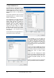
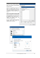
Clock Mode
Sample Rate
Sets the currently used sample rate. Offers a central and comfortable way of configuring the
sample rate of all WDM devices to the same value, as since Vista the audio software is no
longer allowed to set the sample rate. However, an ASIO program can still set the sample rate
by itself.
During record/playback the selection is greyed out, so no change is possible.
Clock Source
The unit can be configured to use its own clock (Internal = Master) or the digital input signal
(Input 1-4 = Slave). If the external source isn't available (Input Status No Lock), the unit will
change to the internal clock. The current clock source is displayed as Current.
Input Status
Indicates presence of a valid signal at the optical input 1-4 (Lock, No Lock) and whether the
signal is synchronous (Sync). The third column shows the sample frequency detected by the
hardware (coarse recognition, 32 kHz, 44.1 kHz, 48 kHz etc.). In Clock Mode the clock refer-
ence is shown. See also chapter 26.1.