User's Guide Digiface USB The Optical Box ™ 24 Bit / 192 kHz 9 TotalMix ™ SteadyClock III ™ SyncCheck USB 2.
General 1 2 3 4 5 Introduction ...............................................................6 Package Contents .....................................................6 System Requirements ..............................................6 Brief Description and Characteristics.....................6 First Usage - Quick Start 5.1 Connectors – LEDs .................................................7 5.2 Quick Start ..............................................................
TotalMix FX 19 TotalMix: Routing and Monitoring 19.1 Overview .............................................................. 32 19.2 The User Interface ............................................... 34 19.3 The Channels....................................................... 35 Settings.............................................................. 37 19.4 Section Control Room.......................................... 38 19.5 The Control Strip.................................................. 39 19.5.
User's Guide Digiface USB © RME
User's Guide Digiface USB General User's Guide Digiface USB © RME 5
1. Introduction Thank you for choosing RME’s Digiface USB. This compact, portable audio interface is capable of transferring digital audio data directly to Windows and Mac computers. The latest Plug and Play technology guarantees a simple installation, even for the inexperienced user. Numerous unique features as well as RME's robust drivers enable a quick, efficient and comfortable operation of the Digiface USB. The package contains drivers for Windows Vista / 7 / 8 / 10 and Mac OS X x86 (Intel).
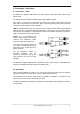
5. First Usage – Quick Start 5.1 Connectors – LEDs The front of the Digiface USB features the USB connector, five status LEDs and the headphone output. The USB power LED indicates sufficient power supply (USB bus power). Sync LEDs 1 to 4 show the current status of all optical inputs. With no input signal they stay dark. With recognized but not synchronous ADAT or SPDIF signal they flash. With a valid and synchronous input signal they stay constantly lit. USB 2.
User's Guide Digiface USB © RME
User's Guide Digiface USB Installation and Operation – Windows User's Guide Digiface USB © RME 9
6. Driver and Firmware 6.1 Driver Installation RME is constantly improving their drivers - the included Driver CD is most probably already outdated when unpacking the product. Please download the latest drivers from the RME website at http://rme.to/usbe. Unzip the downloaded file and start the driver installation with rmeinstaller.exe. If internet access is not available insert the RME Driver CD into your CD-ROM drive. The driver installer is located in the directory \Madiface USB. Start rmeinstaller.
6.3 Firmware Update The Flash Update Tool updates the firmware of the Digiface USB to the latest version. It requires an already installed driver. Start the program fut_mfusb.exe. The Flash Update Tool displays the current revision of the Digiface USB's firmware, and whether it needs an update or not. If so, then simply press the 'Update' button. A progress bar will indicate when the flash process is finished (Verify Ok). After the update the Digiface USB needs to be reset.
7. Configuring the Digiface USB 7.1 Settings Dialog - General Configuration of the Digiface USB is done via its own settings dialog. The panel 'Settings' can be opened: • by clicking on the fire symbol in the Task Bar's notification area The mixer of the Digiface USB (TotalMix FX) can be opened: • by clicking on the FX symbol in the Task Bar's notification area The hardware of the Digiface USB offers a number of helpful, well thought-out practical functions and options which affect how the card operates.
Limit ASIO to 32 Channels A well-known 'professional' DAW software crashes when presented with more than 32 ASIO channels. This workaround removes the phones output, which can still be accessed and used via TotalMix FX. Buffer Size The setting Buffer Size determines the latency between incoming and outgoing ASIO and WDM data, as well as affecting system stability (see chapter 7.1 / 9). USB Diagnosis shows specific USB transmission errors (CRC5, usually 0) and general errors.
7.2 Option WDM Devices The WDM Devices configuration has one button to enter the edit dialog, a status display showing the number of currently enabled WDM devices, and a listbox to select between Stereo or Multi-Channel devices. The number represents both record and playback devices, so ‘1’ means one input and one output device. The screenshot to the right shows the stereo WDM devices available with the Digiface USB, and that only ADAT 1/2 has been activated. Any number can be activated.
Changing to the tab Speaker presents a list of all currently activated WDM devices. Any of these can now get the Speaker property. Please note that defining more than one device as Speaker usually makes no sense, and the speakers also don’t get numbered or renamed in Windows, so it is impossible to find out which one is which. After leaving the dialog with OK the WDM devices are reloaded so Windows sees their new properties. You can now assign any playback mode, from stereo to 7.
8. Operation and Usage 8.1 Playback In the audio application being used, Digiface USB must be selected as output device. It can often be found in the Options, Preferences or Settings menus, as Playback Device, Audio Devices, Audio etc. Increasing the number and/or size of audio buffers may prevent the audio signal from breaking up, but also increases latency i.e. output is delayed. Note: Since Vista the audio application can no longer control the sample rate under WDM.
8.3 Channel Count under WDM The Digiface USB ADAT optical interface offers sample rates of up to 192 kHz. For this to work single-channel data is spread to two or four ADAT channels using the Sample Multiplexing technique. Therefore the number of channels is reduced to 16 or 8 respectively. Whenever the Digiface USB changes into Double Speed (88.2/96 kHz) or Quad Speed mode (176.4/192 kHz) all devices no longer available vanish automatically.
8.6 Clock Modes - Synchronization In the digital world, all devices must be either Master (clock source) or Slave (clock receiver). Whenever several devices are linked within a system, there must always be a single master clock. ! A digital system can only have one master! If the Digiface USB’s clock mode is set to 'Internal', all other devices must be set to ‘Slave’. The Digiface USB utilizes a very user-friendly, intelligent clock control, called AutoSync.
9. Operation under ASIO 9.1 General Start the ASIO software and select ASIO MADIface USB as the audio I/O device or the audio driver. The Digiface USB supports ASIO Direct Monitoring (ADM). 9.2 Channel Count under ASIO The Digiface allows the use of sample rates up to 192 kHz via the ADAT interface. For this to work single-channel data is spread to two or four channels using the Sample Multiplexing technique. Therefore the number of channels is reduced to 16 or 8 respectively.
9.3 Known Problems If a computer does not provide sufficient CPU-power and/or sufficient USB-bus transfer rates, then drop outs, crackling and noise will appear. Such effects can be avoided by using a higher buffer setting/latency in the Settings dialog of the Digiface USB. Furthermore PlugIns should be deactivated temporarily to make sure they do not cause these problems. More information can be found in chapter 25.2. Another common source of trouble is incorrect synchronization.
11. DIGICheck Windows The DIGICheck software is a unique utility developed for testing, measuring and analysing digital audio streams. Although this Windows software is fairly self-explanatory, it still includes a comprehensive online help. DIGICheck 5.90 operates as multi-client ASIO host, therefore can be used in parallel to any software, with both inputs and outputs (!). The following is a short summary of the currently available functions: • Level Meter.
12. Hotline – Troubleshooting The input signal cannot be monitored in real-time • ASIO Direct Monitoring has not been enabled within the DAW, and/or monitoring has been disabled globally (TotalMix Options). The 8 ADAT channels don’t seem to work • The optical output has been switched to SPDIF in the Settings dialog. Playback works, but record doesn’t • Check that there is a valid signal at the input. If so, the current sample frequency is displayed in the Settings dialog.
User's Guide Digiface USB Installation and Operation – Mac OS X User's Guide Digiface USB © RME 23
13. Driver and Firmware 13.1 Driver Installation RME is constantly improving their drivers - the included Driver CD is most probably already outdated when unpacking the product. Please download the latest drivers from the RME website at http://rme.to/usbe. Unzip the downloaded file and start the driver installation by doubleclicking Fireface USB.pkg. If internet access is not available install the drivers from the RME Driver CD, located in the folder Fireface USB.
13.3 Firmware Update The Flash Update Tool updates the firmware of the Digiface USB to the latest version. It requires an already installed driver. Start the program Fireface USB Flash. The Flash Update Tool displays the current revision of the Digiface USB firmware and whether it needs an update or not. If so, simply press the 'Update' button. A progress bar will indicate when the flash process is finished (Verify Ok). After the update the unit needs to be reset.
14. Configuring the Digiface USB 14.1 Settings Dialog Configuring the Digiface USB is done via its own settings dialog. Start the program Fireface USB Settings. The mixer of the Digiface USB (TotalMix FX) can be configured by starting the program Totalmix. The Digiface USB’s hardware offers a number of helpful, well thought-out practical functions and options which affect how the card operates.
14.2 Clock Modes - Synchronization In the digital world, all devices must be either Master (clock source) or Slave (clock receiver). Whenever several devices are linked within a system, there must always be a single master clock. ! A digital system can only have one master! If the Digiface USB’s clock mode is set to 'Internal', all other devices must be set to ‘Slave’. The Digiface USB utilizes a very user-friendly, intelligent clock control, called AutoSync.
15.3 Channel Count under Core Audio The Digiface USB ADAT optical interface offers sample rates of up to 192 kHz. For this to work single-channel data is spread to two or four ADAT channels using the Sample Multiplexing technique. Therefore the number of channels is reduced to 16 or 8 respectively. It is not possible to change the number of Core Audio devices without a reboot of the computer. Therefore whenever the Digiface USB changes into Double Speed (88.2/96 kHz) or Quad Speed mode (176.
17. DIGICheck Mac The DIGICheck software is a unique utility developed for testing, measuring and analysing digital audio streams. Although this Windows software is fairly self-explanatory, it still includes a comprehensive online help. DIGICheck 0.71 operates in parallel to any software, showing all input data. The following is a short summary of the currently available functions: • Level Meter. High precision 24-bit resolution, 2/8/34 channels.
19. Hotline – Troubleshooting The unit and drivers have been installed correctly, but playback does not work: • Is Digiface USB listed in the System Profiler?. • Has Digiface USB been selected as current playback device in the audio application? The 8 ADAT channels don’t seem to work • The ADAT output has been switched to SPDIF in the Settings dialog. Playback works, but record doesn’t: • Check that there is a valid signal at the input.
User's Guide Digiface USB TotalMix FX User's Guide Digiface USB © RME 31
19. Routing and Monitoring 19.1 Overview The Digiface USB includes a powerful digital real-time mixer, based on RME’s unique, samplerate independent TotalMix technology. It allows for practically unlimited mixing and routing operations, with all inputs and playback channels simultaneously, to any hardware outputs. Here are some typical applications for TotalMix: • Setting up delay-free submixes (headphone mixes). The Digiface USB allows for up to 17 fully independent stereo submixes.
User's Guide Digiface USB © RME 33
19.2 The User Interface The visual design of the TotalMix mixer is a result of its capability to route hardware inputs and software playback channels to any hardware output. The Digiface USB has 32 input channels, 34 software playback channels, and 34 hardware output channels: TotalMix can be used in the above view (View Options 2 Rows).
19.3 The Channels A single channel can be switched between mono and stereo mode. The mode is set in the channel settings. Channel name. The name field is the preferred place to select a channel by a mouse click. A double click opens a dialog to assign a different name. The original name will be shown when activating the option Names in the View Options. Panorama. Routes the input signal freely to the left and right routing destination (lower label, see below).
The lowest field shows the current routing target. A mouse click opens the routing window to select a routing target. The list shows all activated routings of the current channel by arrows in front of the listed entries, the current one is shown in bold letters. An arrow is only shown with an activated routing. A routing is seen as activated when audio data is sent. As long as the fader is set to −∞ the current routing will be shown in bold letters, but not have an arrow in the front. Trim Gain.
A click on the tool symbol opens the channel’s Settings panel. The panel includes the following elements: Stereo. Switches the channel to mono or stereo mode. Width. Setting the stereo width. 1.00 equals full stereo, 0.00 mono, 1.00 swapped channels. MS Proc. Activates M/S processing within the stereo channel. Monaural information is sent to the left channel, stereo information to the right. Phase L. Inverts the phase of the left channel by 180°. Phase R. Inverts the phase of the right channel by 180°.
19.4 Section Control Room In the section Control Room the menu Assign is used to define the Main Out which is used for listening in the studio. For this output the functions Dim, Recall, Mono, Talkback and External Input are automatically applied. On the unit the button DIM also follows this assignment. Additionally the channel will be shifted from the Hardware Outputs into the Control Room section, and renamed Main. The same happens when assigning Main Out B or the Phones.
19.5 The Control Strip The Control Strip on the right side combines different functions that are either required globally, or constantly used, and therefore should not be hidden in a menu. Still using the menu entry Window, Hide Control Strip, the Control Strip is shifted out of the visible area to gain more space for other elements. The areas described in the following chapters can be minimized by a click on the arrow in their title bar. Device selection.
19.5.1 View Options The field View Options combines different functions of routing, the level meters and the mixer view. Routing Mode ¾ Submix: The Submix view (default) is the preferred view and delivers the quickest overview, operation and understanding of TotalMix. The click on one of the Hardware Output channels selects the respective submix, all other outputs are darkened. At the same time all routing fields are set to this channel.
19.5.2 Snapshots - Groups Snapshots. Snapshots include all mixer settings, but no graphical elements like window positions, window size, number of windows, visible EQs or Settings, scroll states, Presets etc. Only the state wide/narrow of the channels is registered. Moreover the Snapshot is only temporarily stored. Loading a Workspace causes the loss of all stored Snapshots, when these all had not been saved before in a Workspace, or separately via File / Save Snapshot as.
19.5.3 Channel Layout - Layout Presets To maintain overview within TotalMix FX channels can be hidden. Channels can also be excluded from being remoted. Under Options / Channel Layout a dialog lists all I/Os with their current state. Selecting one or several channels enables the options to the right: ¾ ¾ ¾ Hide Channel in Mixer/Matrix. The selected channels are no longer shown in TotalMix FX, nor are they available via MIDI or OSC remote control. Hide Channel in MIDI Remote 1-4.
After finishing those settings the whole state can be stored as Layout Preset. A click on Store and the desired memory slot makes the current channel layout recallable anytime. The button All makes all channels temporarily visible again. With a simple click on a button it will then be possible to easily switch views of only the channels involved with the mixing of the drum section, the horn section, the violins, or any other useful view.
19.6 Preferences The dialog Preferences can be opened via the Options menu or directly via F2. Level Meters ¾ Full scale samples for OVR. Number of consecutive samples to trigger an over detection (1 to 10). ¾ Peak Hold Time. Hold time of the peak value. Adjustable from 0.1 up to 9.9 s. ¾ RMS +3 dB. Shifts the RMS value by +3 dB, so that full scale level is identical for Peak and RMS at 0 dBFS. Mixer Views ¾ FX Send follows highest Submix. ¾ FX Send follows Main Out.
Graphics ¾ Use D2D (Change requires restart). Default on. Can be deactivated to use a compatible but CPU-taxing graphics mode, in case graphics problems show up. ¾ Brightness correction. Set TotalMix FX screen brightness to your taste, matching the monitor setting or the environment. Store Setting for (Windows only) ¾ All Users (Restart required). See next chapter. Special Options ¾ Lock User Interface. Default off. Can be activated to freeze the current mix state.
19.7 Settings The dialog Settings can be opened via the Options menu or directly via F3. 19.7.1 Mixer Page On the mixer page some typical settings for the mixer operation are set, like Talkback source, Dim amount when Talkback is active, the stored main volume or the input used for the External Input function. Talkback ¾ Input. Selects the input channel of the Talkback signal (microphone in control room). Default: None. ¾ Dim. Amount of attenuation of the signals routed to the Phones in dB.
19.7.2 MIDI Page The MIDI page has four independent settings for up to four MIDI remote controls, using CC commands or the Mackie Control protocol. Index Select one of four settings pages and thus remote controls. Settings are remembered automatically. To activate or deactivate any of the four remote controls check or uncheck ‘In Use’. MIDI Remote Control ¾ MIDI In. Input where TotalMix receives MIDI Remote data. ¾ MIDI Out. Output where TotalMix sends MIDI Remote data. ¾ Disable MIDI in background.
19.7.3 OSC Page The OSC page has four independent settings for up to four MIDI remote controls via Open Sound Control (OSC). This is a network based remote protocol that can be used for example by Apple’s iPad with the app TouchOSC or Lemur to wirelessly remote control TotalMix FX running on a Mac or Windows computer. Index Select one of four settings pages and thus remote controls. Settings are remembered automatically. To activate or deactivate any of the four remote controls check or uncheck ‘In Use’.
19.7.4 Aux Devices The RME OctaMic XTC is a highly flexible hi-quality 8-channel microphone, line and instrument preamp with integrated ADconversion to ADAT, AES/EBU and MADI, plus 4 channels of DA-conversion for monitoring. It can be used as universal front-end for the Digiface USB and other interfaces. To simplify operation the most important parameters of the XTC (gain, 48V, Inst/PAD, AutoSet) can be controlled directly from the TotalMix FX input channels.
19.8 Hotkeys and Usage TotalMix FX has many hotkeys and mouse/hotkey combinations to speed up and simplify the usage. The below description refers to Windows. On Mac substitute Ctrl in the below list with the command key (u). The Shift key enables a fine-tuning of the gain with all faders and in the Matrix. On all knobs it will speed up the setting. A click on a fader with held down Shift key adds the fader to the temporary fader group.
19.9 Menu Options Deactivate Screensaver: When active (checked) any activated Windows screensaver will be disabled temporarily. Always on Top: When active (checked) the TotalMix window will always be on top of the Windows desktop. Note: This function may result in problems with windows containing help text, as the TotalMix window will even be on top of those windows, so the help text isn't readable. Enable MIDI / OSC Control: Activates external MIDI control of the TotalMix mixer.
¾ Total Reset. Playback routing 1:1 with mixdown to Main Out. Switches off all other functions. 19.10 Menu Window Zoom Options 100%, 135%, 200%. Depending on the size of the monitor and the current resolution TotalMix FX might be much too small and the controls too tiny to easily operate them. Together with the 2 Row mode these options give a lot of different window sizes that suit all monitors and resolutions currently existing. Hide Control Strip.
20.3 Operation Using the Matrix is a breeze. It is very easy to indentify the current crosspoint, because the outer labels light up in orange according to the mouse position. ¾ If input 1 is to be routed to output 1, use the mouse and click one time on crosspoint In 1 / AN 1 with held down Ctrl key. Two green 0.0 dB field pop in, another click removes them.
21.5 Copy and Paste everywhere The above three tips use functions found in the right click context menu available on all channels of the TotalMix FX mixer view. These menus are also available in the Matrix, but only directly on the channel labels. They are self-explanatory and automatically adjust to where the click is performed. The input channels offer Clear, Copy input, Paste the input mix and Paste its FX. On a playback channel Copy, Paste and Clear the playback mix are available.
The block diagram shows how the software's input signal is played back, and fed back from the Hardware Output to the software input. Recording a Software's playback In real world application, recording a software's output with another software will show the following problem: The record software tries to open the same playback channel as the playback software (already active), or the playback one has already opened the input channel which should be used by the record software.
22. MIDI Remote Control 22.1 Overview TotalMix can be remote controlled via MIDI. It is compatible to the widely spread Mackie Control protocol, so TotalMix can be controlled with all hardware controllers supporting this standard. Examples are the Mackie Control, Tascam US-2400 or Behringer BCF 2000. Additionally, the stereo output faders (lowest row) which are set up as Main Out in the Control Room section can also be controlled by the standard Control Change Volume via MIDI channel 1.
22.3 Setup Open the Preferences dialog (menu Options or F3). Select the MIDI Input and MIDI Output port where your controller is connected to. When no feedback is needed select NONE as MIDI Output. Check Enable MIDI Control in the Options menu. 22.4 Operation The channels being under Mackie MIDI control are indicated by a colour change of the name field, black turns to brown. The 8-fader block can be moved horizontally and vertically, in steps of one or eight channels.
22.5 MIDI Control The hardware output set up as Main Out can be controlled by the standard Control Change Volume via MIDI channel 1. With this, the main volume of the Digiface USB is controllable from nearly any MIDI equipped hardware device. Even if you don't want to control all faders and pans, some buttons are highly desirable to be available in 'hardware'. These are mainly the Talkback and the Dim button, and the monitoring options (listen to Phones submixes).
Examples for sending MIDI strings: - Set input 1 to 0 dB: B0 66 68 - Set input 5 to maximum attenuation: B1 6A 0 - Set playback 1 to maximum: B4 66 7F - Set Output 3 to 0 dB: B8 68 68 Note: Sending MIDI strings requires the use of programmer's logic for the MIDI channel, starting with 0 for channel 1 and ending with 15 for channel 16.
23. DAW Mode Users that work exclusively with their DAW software, and don’t want to use TotalMix FX for additional routing tasks, need a way to be sure that TotalMix FX currently doesn’t change the DAW’s routing.
User's Guide Digiface USB Miscellaneous User's Guide Digiface USB © RME 61
24. Technical Specifications Input Optical ADAT / SPDIF • 4 x TOSLINK, format according to Alesis specification • SPDIF compatible (IEC 60958) • Standard: 32 channels 24 bit, up to 48 kHz • Double Speed (S/MUX): 16 channels 24 bit 96 kHz • Quad Speed (S/MUX4): 8 channels 24 bit 192 kHz • Bitclock PLL ensures perfect synchronisation even in varispeed operation • Lock range: 31.
25. Technical Background 25.1 Lock and SyncCheck Digital signals consist of a carrier and the data. If a digital signal is applied to an input, the receiver has to synchronize to the carrier clock in order to read the data correctly. To achieve this, the receiver uses a PLL (Phase Locked Loop). As soon as the receiver meets the exact frequency of the incoming signal, it is locked. This Lock state remains even with small changes of the frequency, because the PLL tracks the receiver's frequency.
25.2 USB Audio USB audio is in several ways different from PCI based audio interfaces. The Digiface USB even more, as it tries to use the USB standard’s full potential. Transmitting 32 channels simultaneously in both directions therefore requires modern hardware. While the Digiface USB will work on older computers with for example a Core 2 Duo CPU and ICH 9 as USB hub, the CPU load is noticeable and DPC is raised from the underlying USB driver of the operating system.
26. Warranty Each individual Digiface USB undergoes comprehensive quality control and a complete test at IMM before shipping. The usage of high grade components should guarantee a long and trouble-free operation of the unit. If you suspect that your product is faulty, please contact your local retailer. Do not open the device by yourself as it may get damaged. It has been sealed with tamper-evident material, and your warranty is void if those seals have been damaged.
28. Declaration of Conformity CE This device has been tested and found to comply with the limits of the European Council Directive on the approximation of the laws of the member states relating to electromagnetic compatibility according to RL2004/108/EG, and European Low Voltage Directive RL2006/95/EG. FCC This device complies with Part 15 of the FCC Rules.