
User Manual

22
User's Guide ADI-4 DD © RME
13. Connector Pinouts
D-Sub
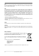
The 25 pin D-sub connector provides all 4 AES inputs and outputs. The actual pinout is defined
by a special coding connector within the ADI-4 DD. To gain access to the coding connector, the
cover has to be removed. The coding connector is attached to a flat ribbon cable, and can be
plugged into three different multipin connectors.
X229: Euphonix
X230: Yamaha
X231: Tascam / Digidesign
X231 is the factory's default setting, and resides next to the front plate. The other side of the
cable is plugged into X228. The position of X228 is fixed and must not be changed.
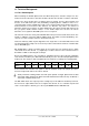
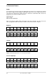
Euphonix:
Signal In
1/2+
In
1/2-
In
3/4+
In
3/4-
In
5/6+
In
5/6-
In
7/8+
In
7/8-
D-Sub 15 2 4 16 18 5 7 19
Signal Out
1/2+
Out
1/2-
Out
3/4+
Out
3/4-
Out
5/6+
Out
5/6-
Out
7/8+
Out
7/8-
D-Sub 21 8 10 22 24 11 13 25
GND is connected to pins 3, 6, 9, 12, 14, 17, 20, 23. Pin 1 is not connected.
Yamaha:
Signal In
1/2+
In
1/2-
In
3/4+
In
3/4-
In
5/6+
In
5/6-
In
7/8+
In
7/8-
D-Sub 1 14 2 15 3 16 4 17
Signal Out
1/2+
Out
1/2-
Out
3/4+
Out
3/4-
Out
5/6+
Out
5/6-
Out
7/8+
Out
7/8-
D-Sub 5 18 6 19 7 20 8 21
GND is connected to pins 9, 10, 11, 12, 13, 22, 23, 24, 25.
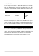
Tascam / Digidesign:
Signal In
1/2+
In
1/2-
In
3/4+
In
3/4-
In
5/6+
In
5/6-
In
7/8+
In
7/8-
D-Sub 24 12 10 23 21 9 7 20
Signal Out
1/2+
Out
1/2-
Out
3/4+
Out
3/4-
Out
5/6+
Out
5/6-
Out
7/8+
Out
7/8-
D-Sub 18 6 4 17 15 3 1 14
GND is connected to pins 2, 5, 8, 11, 16, 19, 22, 25. Pin 13 is not connected.