
User Manual

User's Guide ADI-4 DD © RME
17
10. Conversion Modes and Notes
In this chapter the ADI-4 DD's conversion modes are listed.
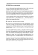
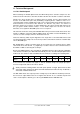
10.1 8-channel AES to ADAT Converter (96 kHz)
SOURCE: AES
Remark: For sample rates higher than 56 kHz the DS LED lights up, and the outputs automati-
cally work in Sample Split mode. Each output port (OUT 1 / OUT 2) then carries 4 channels.
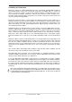
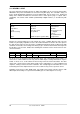
10.2 8-channel AES to 2 x ADAT Splitter (48 kHz)
SOURCE: AES
Remark: For sample rates below 56 kHz the outputs OUT 1 and OUT 2 will carry the same
data. Thus two outputs each can be used for ADAT (splitter).
10.3 2-channel AES to 8-channel ADAT Splitter (96 kHz)
SOURCE: AES
Remark: If only one AES input is being fed, the ADI-4 DD automatically switches to a distribu-
tion mode. The input signal will then be copied to all stereo output channels (splitter 1 to 4).
Because OUT 1/OUT 2 carry the same data, the input signal is split to eight stereo pairs for
ADAT.
For sample rates above 56 kHz the DS LED lights up, and the outputs operate in Sample Split
mode. Each output (OUT 1/OUT 2) then carries 4 channels.
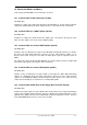
10.4 2-channel AES to 8-channel AES Splitter (96 kHz)
SOURCE: AES
Remark: If only one AES input is being fed with a valid signal, the ADI-4 DD automatically
switches to a distribution mode. The input signal will be copied to all stereo output channels
(splitter 1 to 4). Bridging the ADAT ports with a loop-back cable (OUT 1 to IN 1, OUT 2 to IN 2)
realizes the functionality of a 2-channel to 4 x 2-channel AES splitter.
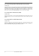
10.5 4-channel AES Double Wire to AES Single Wire Converter (96 kHz)
SOURCE: AES
Remark: If the input signal is present in Double Wire format, DS has to be activated manually in
order to have the AES outputs transmit 4 channels of Double Speed Single Wire data. For this
application, the ADAT ports have to be bridged with a loop-back cable (OUT 1 to IN 1, OUT 2 to
IN 2). ADAT must not be chosen as clock source (SYNC).