User’s Guide Update HDSP and HDSPe Series Windows Driver 4.x incl.
General Overview ....................................................................6 System Requirements ..............................................6 1 2 Driver Installation and Operation Driver Installation and Update .................................8 Major Changes in 4.0 ................................................8 Configuring the HDSP or HDSPe Interface 5.1 Settings Dialog ...........................................................9 5.1.1 The Main Tab ........................................
9 Tips and Tricks ASIO Direct Monitoring ........................................ 38 Copy a Submix..................................................... 38 Delete a Submix................................................... 38 Doubling the Output Signal.................................. 38 Recording a Submix - Loopback.......................... 39 MS Processing..................................................... 40 10 MIDI Remote Control 10.1 Overview ........................................................
Windows Driver 4.
User Guide Update Windows Driver 4.x General Windows Driver 4.
1. Overview The unified Windows driver of the RME HDSP and HDSPe series audio interfaces supports many different units, from the very first PCI-based Digiface up to the PCIe-based HDSPe AES. That makes it possible to use any combination of them (excluding the RPM) as one ASIO device. The Digiface started back in 2001 as the world’s first professional portable multitrack interface, and the first Hammerfall DSP (HDSP) interface ever.
User Guide Update Windows Driver 4.x Driver Installation and Operation Windows Driver 4.
3. Driver Installation and Update First time installation: To simplify installation it is recommended to first install the drivers before the card is put into the computer. But it will also work the other way round. Insert the RME Driver CD into your CD-ROM drive. The driver installer is located in the directory \WDM. Start rmeinstaller.exe and follow the instructions of the installer.
5. Configuring the HDSP or HDSPe Interface This update to the manual addresses the whole HDSP and HDSPe series. The screenshots on the next pages are examples, your particular interface will show some differences. The text describes only the new or changed options which are missing in the current manuals. For all other options please refer to the interface’s original manual. 5.1 Settings Dialog Configuration of the interface is done via its own settings dialog.
5.1.1 The Main Tab Buffer Size The setting Buffer Size determines the latency between incoming and outgoing ASIO and WDM data, as well as affecting system stability. While ASIO can use any offered buffer size, WDM is limited to 256 (XP) or 512 samples (Win 7/8). The driver handles this automatically, higher settings are only applied to ASIO while WDM will stay at 256/512 internally.
5.1.2 The Global Tab This tab includes several options that work on all currently installed cards. Lock Registry Default: off. Checking this option brings up a dialog to enter a password. Changes in the Settings dialog are no longer written to the registry. As the settings are always loaded from the registry when starting the computer, this method provides an easy way to define an initial state for the interface. Optimize Multi-Client Mixing Default: off.
5.1.3 Settings Dialog – Pitch Usually soundcards and audio interfaces generate their internal clock (master mode) by a quartz. Therefore the internal clock can be set to 44.1 kHz or 48 kHz, but not to a value in between. SteadyClock, RME's sensational Low Jitter Clock System, is based on a Direct Digital Synthesizer (DDS). This superior circuitry can generate nearly any frequency with highest precision.
5.2 Clock Modes - Synchronisation In the digital world, all devices must be either Master (clock source) or Slave (clock receiver). Whenever several devices are linked within a system, there must always be a single master clock. A digital system can only have one master! If the card’s clock mode is set to 'Master', all other devices must be set to ‘Slave’. RME interfaces utilize a very user-friendly, intelligent clock control, called AutoSync.
6. WDM Configuration 6.1 Background In the older manuals one will find this explanation why it makes sense to get rid of some WDM devices: WDM Devices Not before Vista the OS had been capable of handling more than 32 WDM stereo devices. Therefore under W2k/XP it often makes sense to intentionally limit their number. Otherwise some channels or MIDI ports might vanish from the system. Today Microsoft gives us even more reasons to deactivate WDM devices that are unused.
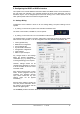
6.2 Option WDM Devices The WDM Devices configuration has one button to enter the edit dialog, a status display showing the number of currently enabled WDM devices, and a listbox to select between Stereo or Multi-Channel devices. The number represents both record and playback devices, so ‘1’ means one input and one output device. The screenshot to the right shows the stereo WDM devices available with the Multiface, and that only Analog 1/2 has been activated. Any number can be activated.
Changing to the tab Speaker presents a list of all currently activated WDM devices. Any of these can now get the Speaker property. Please note that defining more than one device as Speaker usually makes no sense, and the speakers also don’t get numbered or renamed in Windows, so it is impossible to find out which one is which. After leaving the dialog with OK the WDM devices are reloaded so Windows sees their new properties. You can now assign any surround mode, from stereo to 7.
User Guide Update Windows Driver 4.x TotalMix FX Windows Driver 4.
7. TotalMix: Routing and Monitoring 7.1 Overview TotalMix FX is the next generation digital real-time mixer, based on RME’s unique, sample-rate independent TotalMix technology. It allows for practically unlimited mixing and routing operations, with all inputs and playback channels simultaneously, to any hardware outputs. Here are some typical applications for TotalMix: • Setting up numerous delay-free submixes (headphone mixes).
Windows Driver 4.
7.2 The User Interface The visual design of the TotalMix mixer is a result of its capability to route hardware inputs and software playback channels to any hardware output: TotalMix can be used in the above view (View Options 2 Row). However, the default is a vertical alignment in three rows as known from an Inline desk, so that the row Software Playback equals the Tape Return of a real mixing desk: • Top row: Hardware inputs. The level shown is that of the input signal*, i. e. fader independent.
7.3 The Channels A single channel can be switched between mono and stereo mode. The mode is set in the channel settings. Channel name. The name field is the preferred place to select a channel by a mouse click. A double click opens a dialog to assign a different name. The original name will be shown when activating the option Names in the View Options. Panorama. Routes the input signal freely to the left and right routing destination (lower label, see below). The level reduction in center position is -3 dB.
The lowest field shows the current routing target. A mouse click opens the routing window to select a routing target. The list shows all activated routings of the current channel by arrows in front of the listed entries, the current one is shown in bold letters. An arrow is only shown with an activated routing. A routing is seen as activated when audio data is sent. As long as the fader is set to −∞ the current routing will be shown in bold letters, but not have an arrow in the front. Trim Gain.
A click on the tool symbol opens the channel’s Settings panel with differing elements. Stereo. Switches the channel to mono or stereo mode. Width. Setting the stereo width. 1.00 equals full stereo, 0.00 mono, 1.00 swapped channels. MS Proc. Activates M/S processing within the stereo channel. Monaural information is sent to the left channel, stereo information to the right. Not available in some interfaces. Phase L. Inverts the phase of the left channel by 180°. Not available in some interfaces. Phase R.
7.4 Section Control Room In the section Control Room the menu Assign defines the Main Out which is used for listening in the studio. For this output the functions Dim, Recall, Mono, Talkback and External In are automatically applied. Additionally the channel will be shifted from the Hardware Outputs into the Control Room section, and renamed Main. The same happens when assigning Main Out B or the Phones. The original name can be displayed by the function Names in the View Options at any time.
7.5 The Control Strip The Control Strip on the right side is a fixed element. It combines different functions that are either required globally, or constantly used, and therefore should not be hidden in a menu. Device selection. Select the unit to be controlled in case more than one is installed on the computer. Undo / Redo. With the unlimited Undo and Redo changes of the mix can be undone and redone, at any time. Undo/Redo does not cover graphical changes (window size, position, channels wide/narrow etc.
7.5.1 View Options The field Show combines different functions of routing, the level meters and the mixer view. Routing Mode ¾ Submix: The Submix view (default) is the preferred view and delivers the quickest overview, operation and understanding of TotalMix. The click on one of the Hardware Output channels selects the respective submix, all other outputs are darkened. At the same time all routing fields are set to this channel.
7.5.2 Snapshots - Groups Snapshots. Snapshots include all mixer settings, but no graphical elements like window positions, window size, number of windows, visible settings, scroll states etc. Only the state wide/narrow of the channels is registered. Moreover the Snapshot is only temporarily stored. Loading a Workspace causes the loss of all stored Snapshots, when these all had not been saved before in a Workspace, or separately via File / Save Snapshot as.
Hidden channels in Mixer/Matrix are still fully functional. An existing routing/mixing stays active. But as the channel is no longer visible it can not be edited anymore. At the same time the hidden channels are removed from the list of remote controllable channels, to prevent them from being edited unnoticed. Hidden channels in MIDI Remote x are removed from the list of remote controllable channels. Within an 8-channel block of a Mackie compatible control they are skipped.
7.5.4 Scroll Location Markers Another feature to improve overview and working with TotalMix FX are scroll location markers (TotalMix view only). These are displayed automatically when the horizontal size of the TotalMix FX window is smaller than the channel display requires. Shown on the right side of the scrollbar of each row they have four elements: ¾ ¾ ¾ ¾ Arrow to the left. A left mouse click let the channels scroll to the very first one, or most left. 1. Marker number 1.
7.6 Preferences The dialog Preferences can be opened via the Options menu or directly via F2. Level Meters ¾ Full scale samples for OVR. Number of consecutive samples to trigger an over detection (1 to 10). ¾ Peak Hold Time. Hold time of the peak value. Adjustable from 0.1 up to 9.9 s. ¾ RMS +3 dB. Shifts the RMS value by +3 dB, so that full scale level is identical for Peak and RMS at 0 dBFS. Mixer Views ¾ FX Send follows highest Submix. Not available. ¾ Center Balance/Pan when changing Mono/Stereo.
7.6.1 Store for Current or All Users TotalMix FX stores all settings, workspaces and snapshots for the current user in: XP: C:\Documents and Settings\ Username\Local Settings\ Application Data\TotalMixFX Vista/7/8: C.\Users\Username\AppData\Local\TotalMixFX Current User ensures that when workstations are used by several people they all find their own settings. In case the settings should be identical or given for any user, TotalMix FX can be changed to use the All User directory.
7.7.2 MIDI Page The MIDI page has four independent settings for up to four MIDI remote controls, using CC commands or the Mackie Control protocol. Index Select one of four settings pages and thus remote controls. Settings are remembered automatically. To activate or deactivate any of the four remote controls check or uncheck ‘In Use’. MIDI Remote Control ¾ MIDI In. Input where TotalMix receives MIDI Remote data. ¾ MIDI Out. Output where TotalMix sends MIDI Remote data. ¾ Disable MIDI in background.
7.7.3 OSC Page The OSC page has four independent settings for up to four MIDI remote controls via Open Sound Control (OSC). This is a network based remote protocol that can be used for example by Apple’s iPad with the app TouchOSC or Lemur to wirelessly remote control TotalMix FX running on a Mac or Windows computer. Index Select one of four settings pages and thus remote controls. Settings are remembered automatically. To activate or deactivate any of the four remote controls check or uncheck ‘In Use’.
7.7.4 Aux Devices The RME OctaMic XTC is a highly flexible hi-quality 8-channel microphone, line and instrument preamp with integrated AD-conversion to ADAT, AES/EBU and MADI, plus 4 channels of DAconversion for monitoring. It can be used as universal front-end for nearly any RME interface as well as other interfaces. To simplify operation the most important parameters of the XTC (gain, 48V, phase, mute, AutoSet) can be controlled directly from the TotalMix FX input channels.
7.8 Hotkeys and Usage TotalMix FX has many hotkeys and mouse/hotkey combinations to speed up and simplify the usage. The Shift key enables a fine-tuning of the gain with all faders and in the Matrix. On all knobs it will speed up the setting. A click on a fader with held down Shift key adds the fader to the temporary fader group. A click in the fader path with held down Ctrl key will let the fader jump to 0 dB, at the next click to −∞. Same function: Double click of the mouse.
7.9 Menu Options Deactivate Screensaver: When active (checked) any activated Windows screensaver will be disabled temporarily. Always on Top: When active (checked) the TotalMix window will always be on top of the Windows desktop. Note: This function may result in problems with windows containing help text, as the TotalMix window will even be on top of those windows, so the help text isn't readable. Enable MIDI / OSC Control: Activates external MIDI control of the TotalMix mixer.
8. The Matrix 8.1 Overview The mixer window of TotalMix looks and operates similar to mixing desks, as it is based on a conventional stereo design. The matrix display presents a different method of assigning and routing channels, based on a single channel or monaural design. The matrix view has the look and works like a conventional patchbay, adding functionality way beyond comparable hardware and software solutions.
The Matrix not always replaces the mixer view, but it significantly enhances the routing capabilities and - more important - is a brilliant way to get a fast overview of all active routings. It shows you in a glance what's going on. And since the Matrix operates monaural, it is very easy to set up specific routings with specific gains. 9. Tips and Tricks 9.1 ASIO Direct Monitoring Programs that support ADM (ASIO Direct Monitoring - Samplitude, Sequoia, Cubase, Nuendo etc.
9.5 Recording a Submix - Loopback This chapter is not valid for the HDSP MADI, please refer to the original manual (no internal loopback available). HDSP and HDSPe systems include an internal loopback function, from the Hardware Outputs to the recording software. Instead of the signal at the hardware input, the signal at the hardware output is sent to the record software. This way, complete submixes can be recorded without an external loopback cable.
Recording a Software's playback In real world application, recording a software's output with another software will show the following problem: The record software tries to open the same playback channel as the playback software (already active), or the playback one has already opened the input channel which should be used by the record software. This problem can easily be solved.
10. MIDI Remote Control 10.1 Overview TotalMix FX can be remote controlled via MIDI. It is compatible to the widely spread Mackie Control protocol, so TotalMix can be controlled with all hardware controllers supporting this standard. Examples are the Mackie Control, Tascam US-2400 or Behringer BCF 2000. Additionally, the stereo output faders (lowest row) which are set up as Main Out in the Control Room section can also be controlled by the standard Control Change Volume via MIDI channel 1.
10.3 Setup Open the Preferences dialog (menu Options or F3). Select the MIDI Input and MIDI Output port where your controller is connected to. When no feedback is needed select NONE as MIDI Output. Check Enable MIDI Control in the Options menu. 10.4 Operation The channels being under Mackie MIDI control are indicated by a colour change of the name field, black turns to brown. The 8-fader block can be moved horizontally and vertically, in steps of one or eight channels.
10.5 MIDI Control The hardware output set up as Main Out can be controlled by the standard Control Change Volume via MIDI channel 1. With this, the main volume of the RME interface is controllable from nearly any MIDI equipped hardware device. Even if you don't want to control all faders and pans, some buttons are highly desirable to be available in 'hardware'. These are mainly the Talkback and the Dim button, and the monitoring options (listen to Phones submixes).
Examples for sending MIDI strings: - Set input 1 to 0 dB: B0 66 68 - Set input 5 to maximum attenuation: B1 6A 0 - Set playback 1 to maximum: B4 66 7F - Set Output 3 to 0 dB: B8 68 68 Note: Sending MIDI strings requires to use programmer's logic for the MIDI channel, starting with 0 for channel 1 and ending with 15 for channel 16.