
User`s guide


User’s Guide HDSP System HDSP 9652 © RME
9
8. Operation and Usage
8.1 External Connections
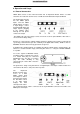
HDSP 9652 consists of the main PCI board and an Expansion Board. All the essential
electronics are located on the PCI card, so it will also work without the Expansion Board.
The main board's bracket
has two ADAT optical
inputs and two ADAT
optical outputs, as well as
a 9-pin D-type socket.
Coaxial S/PDIF input and
output requires plugging
in the adapter cable,
whereby the red phono
socket is the output.
The ADAT1 I/O next to the D-type socket can also be used for optical SPDIF, if this mode is
selected in the Settings dialog.
An input is selected via the Settings dialog (started by clicking on the hammer symbol in the
system tray). Hammerfall accepts the commonly used digital audio formats, SPDIF as well as
AES/EBU. Channel status and copy protection are ignored.
In SPDIF mode, identical signals are available at both the optical and the coaxial outputs. An
obvious use for this would be simply connecting two devices, i.e. using the HDSP 9652
as a splitter.
To receive signals in AES/EBU format,
an adapter cable is required. Pins 2 and 3
of a female XLR plug are connected
individually to the two pins of a phono
plug. The cable shielding is only
connected to pin 1 of the XLR - not to the
phono plug.
The ground-free design using transformers for digital inputs and outputs enables trouble-free
connection to all devices, and perfect hum rejection.
The Expansion
Board's bracket gives
access to a third
ADAT optical input
and output as well as
word clock I/O. Next to
the two BNC sockets
is an LED, which
displays the word
clock input lock status.
The included breakout cable is connected to the 9-pin Mini-DIN connector and realizes two
MIDI inputs and outputs.