
User`s guide

User’s Guide HDSP System HDSP 9652 © RME
16
MME
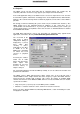
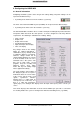
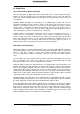
Check Input verifies the current input signal against the settings in the record program. When
de-activated a recording will always be allowed, even with non-valid input signals. This setting
is valid for MME only.
TMS activates the transmission of Channel Status data and Track Marker information of the
SPDIF input.
Buffer Size
The setting Buffer Size determines the latency between incoming and outgoing ASIO and GSIF
data, as well as affecting system stability (see chapter 13). Under Windows MME this setting
determines the DMA buffer size (see chapter 8.5).
SyncCheck
‘SyncCheck’ indicates for ADAT, ADAT Sync, SPDIF and word clock input whether there is a
valid signal (‘Lock’ or ‘No Lock’), or a valid and synchronous signal (‘Sync’). The ‘AutoSync Ref’
display shows the input and frequency of the current sync source.
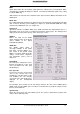
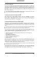
SPDIF In
Defines the input for the SPDIF
signal. 'Coaxial' relates to the phono
socket, 'ADAT1' to the optical
TOSLINK input ADAT1.
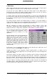
SPDIF Out
The SPDIF output signal is
constantly available at the phono
plug. After selecting 'ADAT1' it is
also routed to the optical output
ADAT1. For further details about the
settings ‘Professional’, ‘Emphasis’
and ‘Non-Audio’, please refer to
chapter 12.
Clock Mode
The card can be configured to use its
internal clock (Master), or the clock
source pre-defined via Pref. Sync
Ref (AutoSync).
Pref. Sync Ref
Used to pre-select the desired clock
source. If the selected source isn't
available the card will change to the
next available one. The currently
used clock source and sample rate is
displayed in the AutoSyncRef
display.
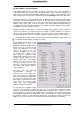
The automatic clock selection checks and changes between the clock sources ADAT optical,
SPDIF, word clock and ADAT Sync. The latter is recommended especially for sample-accurate
transfers under ASIO 2.0.
System Clock
Shows the current clock state of the HDSP system. The system is either Master (using its own
clock) or Slave (AutoSync Ref).