User’s Guide Hammerfall® DSP System HDSP 9652 TotalMix ™ 24 Bit / 96 kHz ü ® SyncAlign ® ZLM ® SyncCheck PCI Busmaster Digital I/O Card 2 + 24 Channels Stereo / ADAT Interface 24 Bit / 96 kHz Digital Audio ADAT Sync In MIDI I/O
Contents 1 2 3 4 5 Introduction............................................................ 4 Package Contents .................................................. 4 System Requirements............................................ 4 Brief Description and Characteristics................... 5 Technical Specifications 5.1 Digital.................................................................... 5 5.2 Digital Interface..................................................... 5 5.3 MIDI .............................
16 17 18 19 20 21 22 23 24 25 The Matrix 16.1 Elements of the Surface .................................... 32 16.2 Operation .......................................................... 32 16.3 Advantages of the Matrix................................... 33 TotalMix Super-Features 17.1 ASIO Direct Monitoring...................................... 33 17.2 Selection and Group based Operation ............... 34 17.3 Copy Routings to other Channels ...................... 34 Hotline - Troubleshooting 18.
1. Introduction Thank you for choosing the Hammerfall DSP. This unique audio system is capable of transferring digital audio data directly to a computer from practically any device equipped with a digital audio interface, be it SPDIF, AES/EBU or ADAT optical. Installation is simple, even for the inexperienced user, thanks to the latest Plug and Play technology and full interrupt-sharing.
4. Brief Description and Characteristics • • • • • • • • • • • • • • • • • Hammerfall design: 0% (zero!) CPU load, even using all 52 ASIO channels All settings can be changed in real-time Enhanced mixed mode: ADAT In, SPDIF In, and all outputs can be used simultaneously 8 available buffer sizes/latencies: 1.
5.4 Transfer Modes: Resolution / Bits per Sample ASIO: • 24 or 32 bit, 4 byte (stereo 8 byte) This format is compatible with 16-bit and 20-bit. Resolutions below 24-bit are handled by the audio application. MME: • 16 bit, 2 byte • 20 bit, 3 byte MSB • 20 bit, 4 byte MSB • 24 bit, 3 byte • 24 bit, 4 byte MSB • 32 bit, 4 byte (stereo 4 byte) (stereo 6 byte) (stereo 8 byte) (stereo 6 byte) (stereo 8 byte) (stereo 8 byte) Channel Interleave operation is limited to single speed operation and 16 bit. 6.
. Driver Installation 7.1 Windows 98/SE/ME After the PCI card has been installed correctly (see 6. Hardware Installation), and the computer has been switched on, Windows will recognize the new hardware component and start its ‘Add New Hardware Wizard’. Insert the RME Driver CD into your CD-ROM drive, and follow further instructions which appear on your computer screen. The driver files are located in the directory \HDSP_w98 on the RME Driver CD.
7.4 Flash Update The Flash Update Tool updates the HDSP 9652's hardware to the latest version. It requires an already installed driver. Start the program fut_xxx_xxx.exe. The Flash Update Tool displays the current revision of the HDSP interface, and whether it needs an update or not. If so, then simply press the 'Update' button. A progress bar shows how several actions are performed. When the flash update process is finished, 'Success' will be displayed.
8. Operation and Usage 8.1 External Connections HDSP 9652 consists of the main PCI board and an Expansion Board. All the essential electronics are located on the PCI card, so it will also work without the Expansion Board. The main board's bracket has two ADAT optical inputs and two ADAT optical outputs, as well as a 9-pin D-type socket. Coaxial S/PDIF input and output requires plugging in the adapter cable, whereby the red phono socket is the output.
8.2 Internal Connections AEB1 IN / CD IN This internal digital input can be used with both SPDIF and ADAT. SPDIF: • Connection to an internal CD-ROM drive with digital audio output. Allows for a direct transfer of digital audio data within the computer. • Connection to SYNC OUT of another card. This internal SPDIF connection can be used to synchronize multiple cards with sample accuracy, and without the need for an external connection.
8.3 Playback The HDSP system can play back audio data in supported formats only (sample rate, bit resolution). Otherwise an error message appears (for example at 22 kHz and 8 bit). In the audio application being used, HDSP must be selected as output device. This can often be found in the Options, Preferences or Settings menus under Playback Device, Audio Devices, Audio etc. We recommend using 24-bit resolution for playback, to make full use of the HDSP’s potential.
8.4 DVD-Playback (AC-3 / DTS / Multichannel) under MME AC-3 / DTS When using popular DVD software player like WinDVD and PowerDVD, their audio data stream can be sent to any AC-3/DTS capable receiver, using the Hammerfall DSP's SPDIF output. For this to work the SPDIF output wave device has to be selected in 'Control Panel/Sounds and Multimedia/Audio'. Also check 'use preferred device only'. You will notice that the DVD software's audio properties now allow to use 'SPDIF Out' or to 'activate SPDIF output'.
8.5 Low Latency under MME (Buffer Size Adjustment) Using Windows 95 or 98 the MME buffer size was nothing to worry about. Latencies below 46 ms were not possible. Meanwhile both computers and operating system have become much more powerful, and since Windows ME/2000/XP latencies far lower can be used. SAWStudio and Sonar allowed to use such low settings from the start. Sequoia was updated in version 5.91, WaveLab in version 3.04.
8.7 Recording Unlike analog soundcards which produce empty wave files (or noise) when no input signal is present, digital I/O cards always need a valid input signal to start recording. To take this into account, RME have added two unique features to the HDSP 9652: a comprehensive I/O signal status display (showing sample frequency, lock and sync status) in the Settings dialog, and the protective Check Input function. If a 48 kHz signal is fed to the input and the application is set to 44.
9. Configuring the HDSP 9652 9.1 General Information Configuring the HDSP system is done using its own settings dialog.
MME Check Input verifies the current input signal against the settings in the record program. When de-activated a recording will always be allowed, even with non-valid input signals. This setting is valid for MME only. TMS activates the transmission of Channel Status data and Track Marker information of the SPDIF input. Buffer Size The setting Buffer Size determines the latency between incoming and outgoing ASIO and GSIF data, as well as affecting system stability (see chapter 13).
9.2 Clock Modes - Synchronization In the digital world, all devices are either the ‘Master’ (clock source) or a ‘Slave’ synchronized to the master. Whenever several devices are linked within a system, there must always be a single master clock. The Hammerfall DSP’s intelligent clock control is very user-friendly, being able to switch between clock modes automatically. Selecting AutoSync will activate this mode. In AutoSync mode, the system constantly scans all digital inputs for a valid signal.
If several digital devices are to be used simultaneously in a system, they not only have to operate with the same sample frequency but also be synchronous with each other. This is why digital systems always need a single device defined as ‘master’, which sends the same clock signal to all the other (‘slave’) devices. RME’s exclusive SyncCheck technology (first implemented in the Hammerfall) enables an easy to use check and display of the current clock status.
10. Word Clock 10.1 Technical Description and Usage Correct interpretation of digital audio data is dependent upon a definite sample frequency. Signals can only be correctly processed or transferred between devices if these all share the same clock, otherwise digital signals are misinterpreted, causing distortion, clicks/crackle and even dropouts. AES/EBU, SPDIF and ADAT are self-clocking, so an additional line for word clock could be considered redundant.
10.3 General Operation The green ‘Lock’ LED at the Expansion Board will light up when the input sees a valid word clock signal. Selecting ‘Word Clock’ in the ‘Clock Mode’ field will switch clock control over to the word clock signal. As soon as there is a valid signal at the BNC jack, 'AutoSync Ref' will display 'Word'. This message has the same function as the green ‘Lock’ LED, but appears on the monitor, i.e.
13. Operation under ASIO 2.0 13.1 General We will use Steinberg’s Cubase VST as an example throughout this chapter. All information provided can easily be adaptated to other programs. Start the ASIO software and select ‘System’ from the Audio menu. Select 'ASIO Hammerfall DSP' as the audio I/O device. The 'ASIO system control' button opens the HDSP’s Settings dialog (see chapter 9, Configuration).
13.3 Synchronization To achieve sample-accuracy between the ADAT recorder and Hammerfall DSP while running Cubase, connect the ADAT sync output with the 9-pin D-type sync input of the HDSP. The ‘Time Code’ field in the Settings dialogue should now show the same position as the ADAT recorder. Double-clicking on the Sync button in Cubase’s transport panel will open the ‘Synchronization’ dialog. Select ASIO 2.
14. Operation under GSIF (Gigasampler Interface) 14.1 Windows 98/SE/ME The GSIF interface of the Hammerfall DSP’s Windows 98/SE/ME driver allows direct operation with Gigasampler and Gigastudio, with up to 26 channels, 96kHz and 24bit. Additionally the driver supports multi-client operation. For example ASIO can use channels 1/2 and Gigastudio (with GSIF) channels 3/4 simultaneously, and so on. Gigasampler/Studio requires a lot of the computer’s calculation power.
15. TotalMix: Routing and Monitoring The Hammerfall DSP system includes a powerful digital real-time mixer. RME’s unique TotalMix technology allows for nearly unlimited mixing and routing with all inputs and playback channels simultaneously.
15.1 Elements of the Surface The visible design of the TotalMix mixer is mainly determined by the architecture of the HDSP system: • Upper row: hardware inputs. The level shown is that of the input signal, i. e. Fader independent. Per fader and routing window, any input channel can be routed and mixed to any hardware output (third row). • Middle row: playback channels (playback tracks of the software).
15.2 Tour de TotalMix In the following chapters we will explain all functions of the surface step by step. Starting up TotalMix, the last settings are recalled automatically. When executing the application for the first time, a default file is loaded, sending all playback tracks 1:1 to the corresponding hardware outputs with 0 dB gain. The faders in the upper row are set to maximum attenuation (called m.a. in the following), so there is no monitoring of the input channels.
15.3 Submix View Such a wide range of possibilities make it difficult to maintain the overview. Because practically all hardware outputs can be used for different submixes, as shown. And when opening the routing windows you might see an army of checkmarks, but you don't get an overwiev, i.e., how the signals come together and where. This problem is removed by the view mode 'Submix'. In this mode, all routing windows jump to the routing pair just being selected.
Using the hotkeys I, O and P the complete row each of Input, Playback and Output channels can be toggled between visible and invisible. Hotkey S switches Submix view on/off. Those four hotkeys have the same functionality as the buttons in the View section of the Quick Access Panel. The Level Meter Setup dialog can be opened via F2 (as in DIGICheck and the Meter Bridge). Hotkey M toggles Master Mute on/off (and with this performs a global mute on/off).
15.7 Presets TotalMix includes 8 factory presets, stored within the program. But the presets can be changed at any time, because TotalMix stores and reads the changed presets from the files preset11.mix to preset81.mix. These files are found in the hidden directory Documents and Settings, , Local Settings, Application Data, RME TotalMix. The first number indicates the current preset, the second number the current card/system.
15.8 Monitor The Monitor section of the Quick Access Panel is only valid for our Windows MME driver, i.e. when using programs like WaveLab, Soundforge, Sonar or Samplitude. Monitor offers two advanced automated monitoring solutions. Monitoring will be controlled either by special commands directly from the recording software (Samplitude/Sequoia/SAWStudio, mode ZLM), or by the recording state itself (mode Mix/Replace).
15.10 Level Meter Having set a new standard with the level meters of DIGICheck, Hammerfall DSP goes even further: The calculation of the Peak, RMS and Over is realized in hardware, in order to be capable of using them independent of the software in use, and to significantly reduce the CPU load. The level meters integrated in TotalMix - considering their size - cannot be compared with the HDSP Meter Bridge (chapter 19.2). Nevertheless they already include many useful functions.
16. The Matrix The mixer window of TotalMix looks and operates similar to mixing desks, as it is based on a conventional stereo design. The matrix display presents a different method of assigning and routing channels, based on a single channel or monaural design. The matrix view of the HDSP mixer looks and works like a conventional patchbay, adding functionality way beyond comparable hardware and software soutions.
16.3 Advantages of the Matrix The Matrix not always replaces the mixer view, but it significantly enhances the routing capabilities and - more important - is a brilliant way to get a fast overview on all active routings. It shows you in a glance what's going on. And since the Matrix operates monaural, it is very easy to set up specific routings with specific gains.
17.2 Selection and Group-based Operation Click on the white name label of channel 1 and 2 in TotalMix. Be sure to have channel 3's fader set to a different position and click on its label too. All three labels have changed to the colour orange, which means they are selected. Now moving any of these faders will make the other faders move too. This is called 'building a group of faders', or ganging faders, maintaining their relative position.
18. Hotline - Troubleshooting 18.1 General The newest information can always be found on our website www.rme-audio.com, section FAQ, Latest Additions. The ADAT timecode is not in sync • The tape is formatted to 48 kHz, but played back at 44.1 kHz (Pitch). This 'Blackface' problem cannot be solved in a satisfactory way. ADAT timecode is running, but Cubase does not start 'Play' automatically • The input displayed in ‘Sync Ref’ is not in sync mode.
Low Latency ASIO operation under Windows 2000/XP on single CPU systems: • To use ASIO at lowest latencies under Windows 2000/XP even when only having one CPU, the system performance has to be optimized for background tasks. Go to Control Panel/System/Advanced/Performance Options. Change the default 'Applications' to 'Background tasks'. The lowest usable latency will drop from 23 ms to around 3 ms. This is no issue when using dual CPU systems. 18.
19. HDSP Software 19.1 DIGICheck 4.0 The DIGICheck software is a unique utility developed for testing, measuring and analysing digital audio streams. Although the DIGICheck software is fairly self-explanatory, it still includes a comprehensive online help. DIGICheck 4.0 operates as multi-client ASIO host, and can therefore be used in parallel to any software, be it MME, ASIO or GSIF, both inputs and even outputs (!). The following is a short summary of the available functions: • Level Meter.
20. Accessories RME offers several optional components, further increasing the flexibility and usability of the HDSP system. Additionally parts of the HDSP system, like the breakout cables, are available seperately. Part Number Description OK05 OK1 OK2 OK3 OK5 OK10 Optical cable, Toslink, 0.5 m (1.5 ft) Optical cable, Toslink, 1 m (3.3 ft) Optical cable, Toslink, 2 m (6.6 ft) Optical cable, Toslink, 3 m (9.9 ft) Optical cable, Toslink, 5 m (16.4 ft) Optical cable, Toslink, 10 m (32.
22. Warranty Each individual Hammerfall DSP undergoes comprehensive quality control and a complete test in a PC environment at RME before shipping. This may cause very slight signs of wear (if it looks like it was used one time before - it was). The usage of high grade components allows us to offer a full two year warranty. We accept a copy of the sales receipt as valid warranty legitimation. RME’s replacement service within this period is handled by the retailer.
24. Diagrams 24.
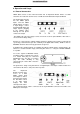
24.2 ADAT Track Routing, ASIO at 96 kHz This diagram shows the signal paths in ASIO double speed mode (88.2 / 96 kHz). The devices available under ASIO have been implemented according to the hardware. Signal routing is identical for record and playback.
24.3 ADAT Track Routing, MME at 96 kHz This diagram shows the signal paths in MME double speed mode (88.2 / 96 kHz). The devices available via wave driver have been designed to avoid conflicts in normal operation, which is why channels 5, 6, 7 and 8 of each ADAT device have been omitted. Signal routing is identical for record and playback.
25. CE and FCC Compliance Statements CE This device has been tested and found to comply with the EN55022 class B and EN50082-1 norms for digital devices, according to the European Council directive on counterpart laws in the member states relating to electromagnetic compatibility (EMVG). FCC This device has been tested and found to comply with the requirements listed in FCC Regulations, part 15 for Class ‘B’ digital devices.