
User`s guide

User's Guide HDSP MADI © RME
7
5. Hardware Installation
Before installing the PCI card, please make sure the computer is switched off and the
power cable is disconnected from mains supply. Inserting or removing the card while the
computer is in operation can cause irreparable damage to both motherboard and card!
1. Disconnect the power cord and all other cables from the computer.
2. Remove the computer's housing. Further information on how to do this can be obtained from
your computer's instruction manual.
3. Important: Before removing the HDSP MADI from its protective bag, discharge any static in
your body by touching the metal chassis of the PC.
4. Prior to installation: Connect the HDSP MADI card to the Expansion Board using the sup-
plied flat ribbon cable.
5. Insert the HDSP MADI firmly into a free PCI slot, press and fasten the screw.
6. Insert the Expansion Board and fasten the screw.
7. Replace the computer's housing.
8. Reconnect all cables including the power cord.
6. Hardware - Connectors
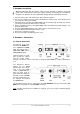
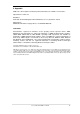
6.1 External Connectors
The bracket of the main
board has two MADI inter-
faces, optical and coaxial
input and output each, a
MADI error LED and the
analog stereo output.
Identical signals are avail-
able at both the optical
and the coaxial output.
Therefore two devices can be connected, i.e. using the HDSP MADI as a splitter (distribution 1
to 2).
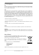
The Expansion Board's
bracket has the word
clock input and output.
Next to the input BNC
socket, a green LED dis-
plays the word clock in-
put's LOCK state. Between
the BNC sockets, 75 Ohm
word clock termination can
be activated and verified
by a yellow LED.
The included breakout cable is connected to the 9-pin Mini-DIN connector and provides two
MIDI inputs and outputs via four 5-pin DIN connectors.
Note
: If neither word clock I/O nor MIDI I/O is required, it is not necessary to install the Expan-
sion Board at all.