
User`s guide


User's Guide HDSP MADI © RME
35
23.3 MIDI
The HDSP MADI offers two MIDI I/O via 5-pin DIN connectors. The MIDI ports are added to the
system by the driver. Using MIDI capable software, these ports can be accessed under the
name MADI MIDI. Using more than one HDSP MADI, a consecutive number is added to the
port name, like MADI MIDI In 1 (2) etc.
The third software-only MIDI port, MADI MIDI In 3 (1) and MADI MIDI Out 3 (1), receives and
transmits MIDI data via MADI. This allows for a direct communication between systems with
HDSP MADI cards. Additionally MIDI data can be transmitted from/to other RME devices with
MADI ports, and both can be MIDI remote controlled without any additional line or cabling be-
tween computer (MADI card) and unit.
24. Word Clock
24.1 Word Clock Input and Output
SteadyClock guarantees an excellent performance in all clock modes. Based on the highly effi-
cient jitter suppression, the HDSP MADI refreshes and cleans up any clock signal, and provides
it as reference clock at the BNC output (see chapter 30.6).
Input
The HDSP MADI's word clock input is active when Pref. Sync Ref in the Settings dialog has
been switched to Word Clock, the clock mode AutoSync has been activated, and a valid word
clock signal is present. The signal at the BNC input can be Single or Double Speed, the HDSP
MADI automatically adapts to it. As soon as a valid signal is detected, the green LED is lit, and
the Settings dialog shows either Lock or Sync (see chapter 30.2).
Thanks to RME's Signal Adaptation Circuit, the word clock input still works correctly even with
heavily mis-shaped, dc-prone, too small or overshoot-prone signals. Thanks to automatic signal
centering, 300 mV (0.3V) input level is sufficient in principle. An additional hysteresis reduces
sensitivity to 1.0 V, so that over- and undershoots and high frequency disturbances don't cause
a wrong trigger.
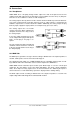
The word clock input is shipped as high impedance type (not terminated). A push switch allows
to activate internal termination (75 Ohms). The switch is found beside the word clock input
socket. Use a small pencil or similar and carefully push the blue switch so that it snaps into its
lock position. The yellow LED will be lit when termination is active. Another push will release it
again and de-activate the termination.
Output
The word clock output of the HDSP MADI is constantly active, providing the current sample
frequency as word clock signal. As a result, in Master mode the provided word clock is defined
by the currently used software or the Settings dialog. In Slave mode the provided frequency is
identical to the one present at the currently chosen clock input. When the current clock signal
fails, the HDSP MADI switches to Master mode and adjusts itself to the next, best matching
frequency (44.1 kHz, 48 kHz etc.).
Selecting 96 kHz – 48K Frame in the Settings dialog causes the output signal to always stay
within the range of 32 kHz to 48 kHz. So at 96 kHz sample rate, the output word clock is 48
kHz.