
Operating instructions


Table Of Contents
- Operation
- Dimensions and assembly
- Dimensions DC 12
- Dimensions of the basic housing DC 12
- Assembly DC 12
- 1. Loosen the screw of the front cover.
- 2. Take off the front cover.
- 3. With a screwdriver lift the base from the controller-print, see illustration right.
- 1. Hold the controller base to the assembly place and mark with an indication pin the mounting holes.
- 2. Drill the mounting holes and provide them with pegs.
- 3. Place the controller base, fit the screws (do not tighten), align the base, then drive the mounting screws fully home.
- Start up
- Troubleshooting
- Technical data
- Index
9
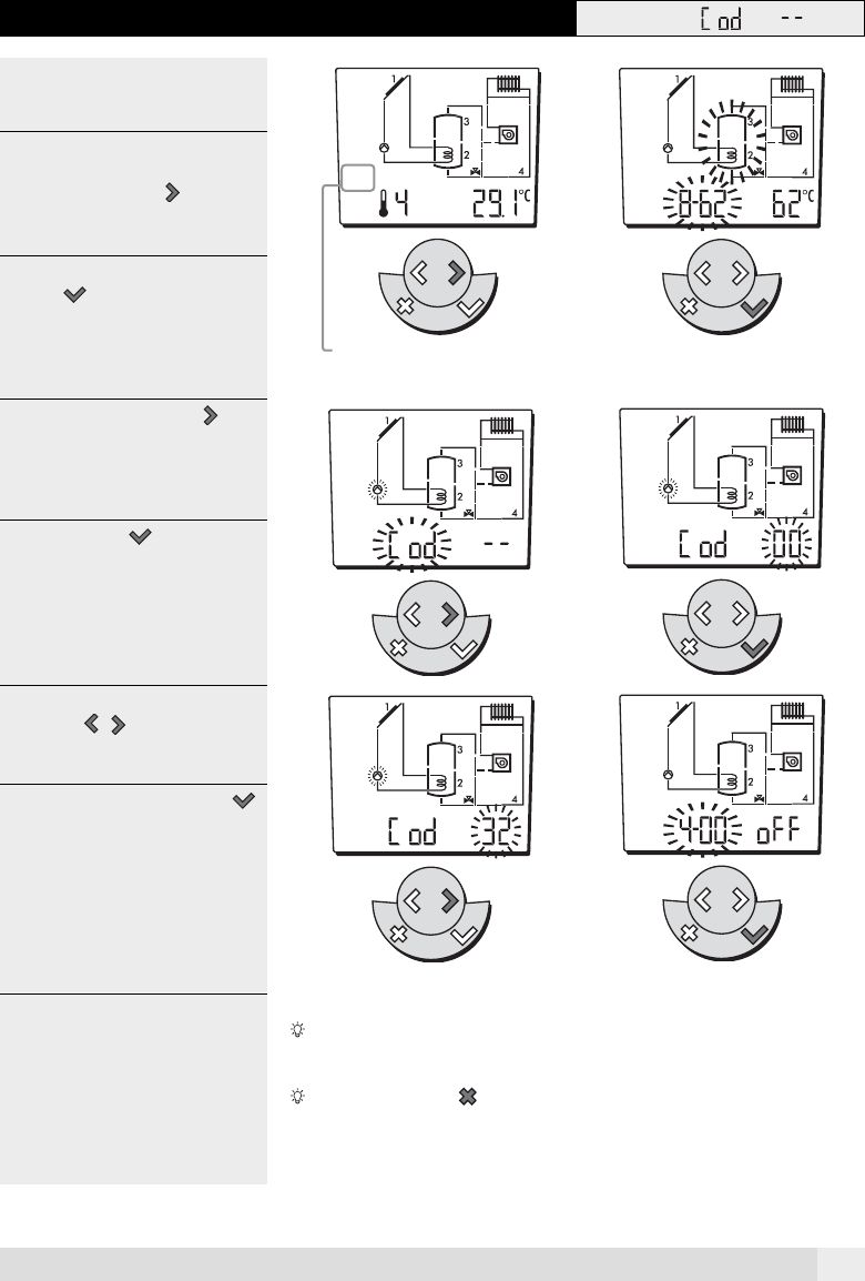
1.5 Changes that need an access code (expert level)
Certain changes should only be made by
experts and are therefore this menu is
protected by an access code.
1 2
Example:
1. To enter the expert menu keeping
pressing the settings
key so
often, until the symbol appears.
2. To view the expert menu, press the
enter key. The first intem that
may be adjusted and its function flas-
hes.
3. Keep pressing the settings key,
until "Cod --" appears.
3 4
4. Press the enter key to enter the
code.
5. Enter the access code ("25") with the
settings
keys.
5 6
6. Confirm the code with the enter
key.
After 2 minutes without a being entered the controller reverts back to its actual
operating mode.
Pressing the cancel key anable you to exit the expert menu. The controller
reverts to its actual operating mode and settings.
SET
SET
Adjuster level
SET
SET
SET
SET
SET
SET
A0805