
Operating instructions


Table Of Contents
- Operation
- Dimensions and assembly
- Dimensions DC 12
- Dimensions of the basic housing DC 12
- Assembly DC 12
- 1. Loosen the screw of the front cover.
- 2. Take off the front cover.
- 3. With a screwdriver lift the base from the controller-print, see illustration right.
- 1. Hold the controller base to the assembly place and mark with an indication pin the mounting holes.
- 2. Drill the mounting holes and provide them with pegs.
- 3. Place the controller base, fit the screws (do not tighten), align the base, then drive the mounting screws fully home.
- Start up
- Troubleshooting
- Technical data
- Index
6
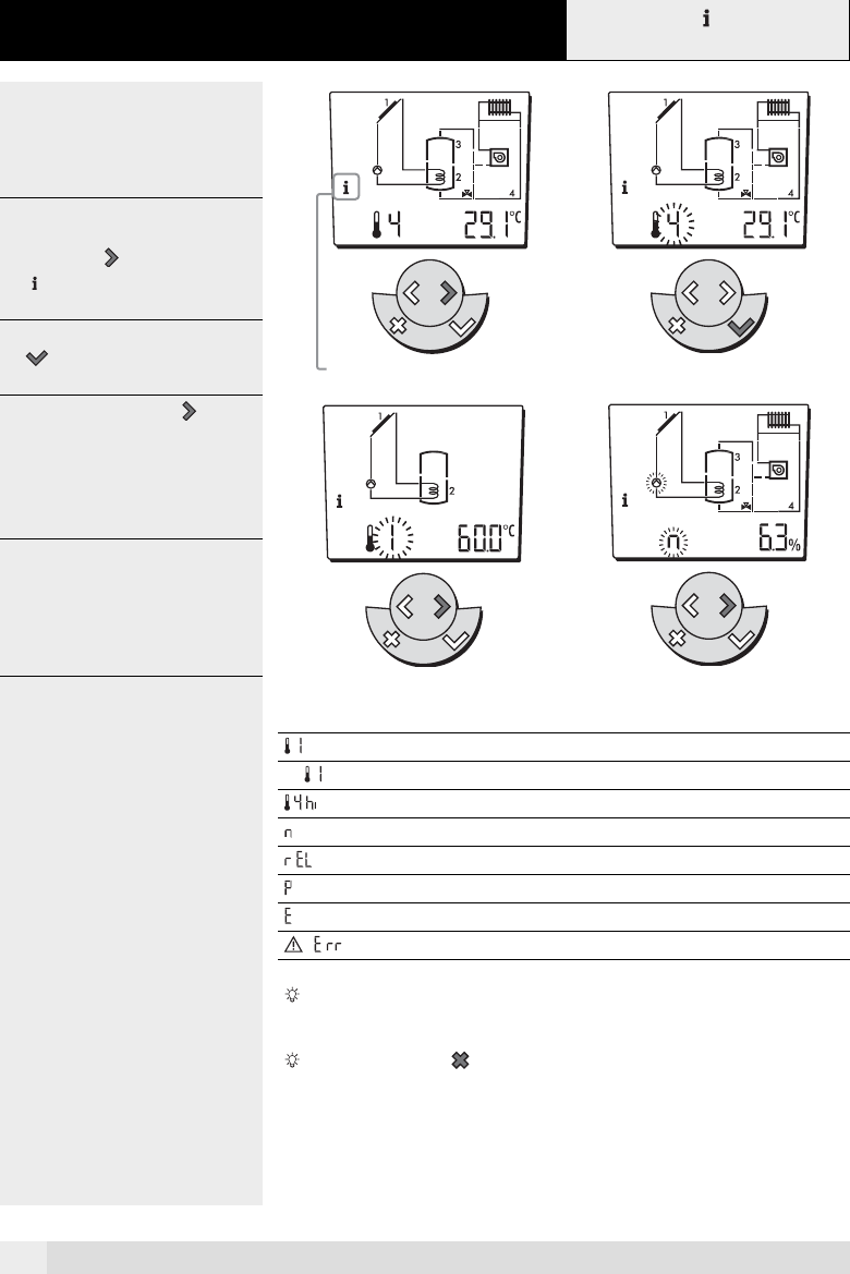
1.2 The information menu, operating data and tempe-
rature value
The information menu enables you to
look at information about the solar sy
-
stem. You can see actual temperatures,
and the way in wich the system is opera
-
ting.
1 2
Example:
1. To enter the information menu, press
the settings
key until the symbol
appears.
2. To look at the data, press the enter
key.
A value flashes on the display.
3. By pressing the settings key, the
temperature values and operating
data can seen in succession.
When the symbol appears on
the display the controller is indicating
the set point of the temprature value.
3 4
4. When you look at the data you will
see the relevant part of the schema
-
tic flashing and it is corresponding
function setting flashing.
Display Description Unit
Measured temperature value °C
Set point of temperature °C
Highest collector temperature in a 24 hour period °C
Collector pump speed %
Reheating pump relay, generator pump or diverter valve -
Collector capacity -
Collector yield -
Information -
After 2 minutes without a being entered the controller reverts back to
its actual operating mode.
Pressing the cancel key anable you to exit the information menu.
The controller reverts to its actual operating mode and settings.
Information level
SET
SET
SET
A0805