
Operating instructions


Table Of Contents
- Operation
- Dimensions and assembly
- Dimensions DC 12
- Dimensions of the basic housing DC 12
- Assembly DC 12
- 1. Loosen the screw of the front cover.
- 2. Take off the front cover.
- 3. With a screwdriver lift the base from the controller-print, see illustration right.
- 1. Hold the controller base to the assembly place and mark with an indication pin the mounting holes.
- 2. Drill the mounting holes and provide them with pegs.
- 3. Place the controller base, fit the screws (do not tighten), align the base, then drive the mounting screws fully home.
- Start up
- Troubleshooting
- Technical data
- Index
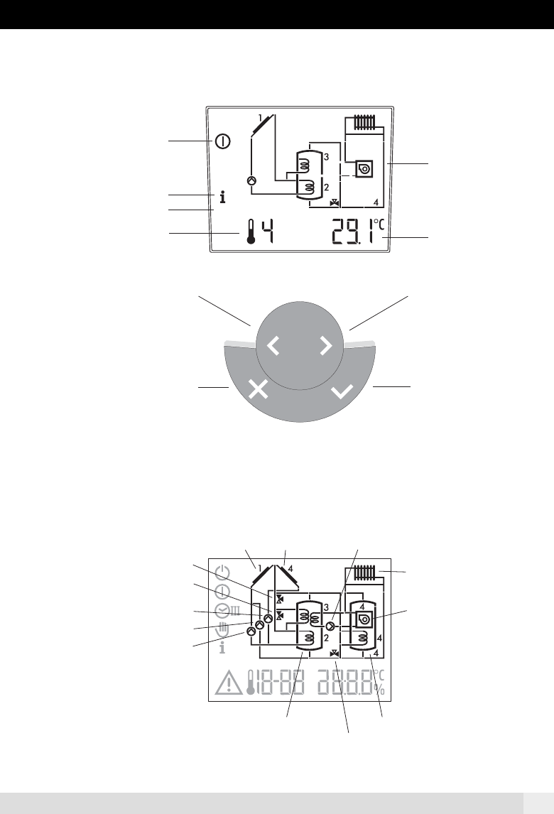
3
Operating
mode
Display value
SET
Identification display value
Hydraulic
diagram
Menu controll
changing settings
Menu controll
changing settings
Cancel
Enter
Display with all segments
Overview of display
SET
Information
Adjuster
Sensor 1
collector 1
Diverting valve storage tank 2
Diverting valve exchanger
Pump collector 2
Pump storeage tank 2
Pump collector 1
Storage tank 1
Sensor 2
Storage tank 2
Diverting valve return
Heating system
Auxillary heater
Sensor 4
Sensor 4
collector 2
Sensor 3
pump rehaet
Display and controls
A0805